Nanobridge M5 wireless LAN link, Part II

After a bit of delay, we were able to return to the WICC transmitter site to install the Wireless LAN link.  The installation was pretty straightforward.  The studio unit was mounted on an existing STL tower on the top of the elevator room, the transmitter unit was mounted on an existing pipe on the roof of the transmitter building.
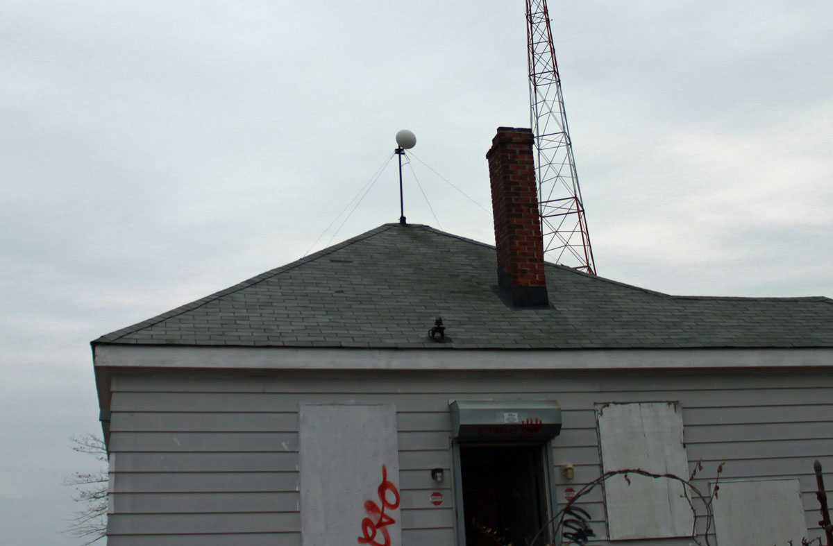
M5 Nanobridge mounted on transmitter building with radome
M5 Nanobridge mounted on transmitter building with RADOME

I included RADOMEs for a couple of reasons; first, there is a lot of critters around of the two-legged and winged kind. The upright two-legged critters may be attracted to the signal-strength lights at night. This unwanted attention could invite the juvenile delinquent’s bored teenagers to throw various objects found laying around on the ground at the antenna, damaging it.  The winged type critter may be inclined to view the feed horn as a good nesting location. The other reason is this site gets a lot of rain, wind, ice, and snow, therefore the RADOMEs afford some protection against the weather.

Aiming the antennas was pretty straightforward, but requires at least two people.  Using landmarks, we aligned the dishes in the general direction of each other.  Both ends of the system were turned on and we had a -89 dBm signal path, and somewhat surprisingly, the radios linked up and my laptop grabbed an IP address via DHCP.  Using the signal strength meter on the side of the antenna, each dish was peaked in turn:
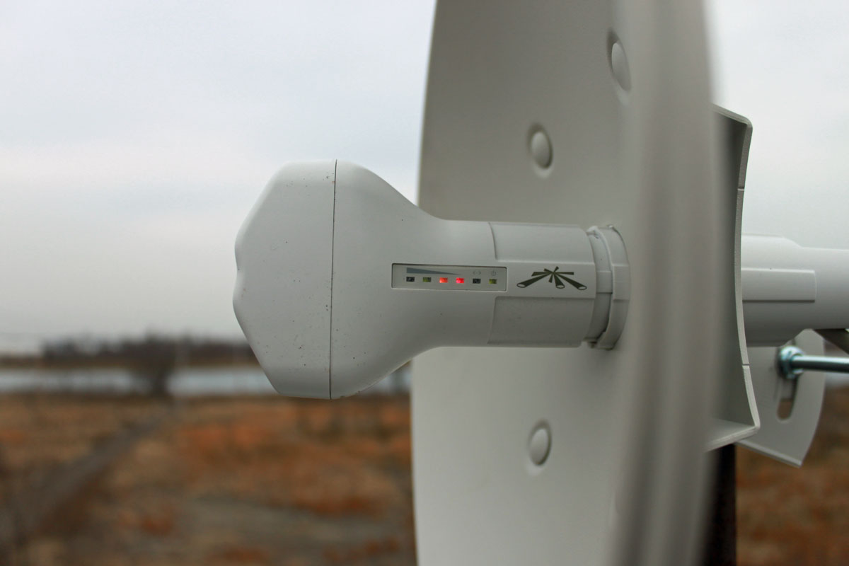
M5 Nanobridge Antenna signal strength meter

Then, somebody on either end went below and looked at the signal strength screen on the web interface while the other end peaked.  In the end, we had about -65 dBm signal strength, which is somewhat less than the -58 dBm predicted.  I think we can do better, so on the next clear day, I am going to peak the signal again.

The data rate initially reported was over 100 MBPS, however, once I started transferring files back and forth, that dropped to about 50 MBPS.  If it is raining, that rate drops to about 35 MBPS, which is still far above what we need this link to do.  As a test, I streamed a youtube video, downloaded a Windows update, loaded several web pages, and checked my email simultaneously.  There were no issues with the data rate while those tasks were being preformed.

It is quite amazing to me that these little inexpensive radios can work so well.  My boss thinks that they will be blown up by lightning during the first thunderstorm of the season.  I don’t know.  There are several of these units have been installed at mountaintop tower sites and have been working for several years without issue.

Next step, installing the IP cameras and warning signs on the fence, setting up the monitoring software, etc.
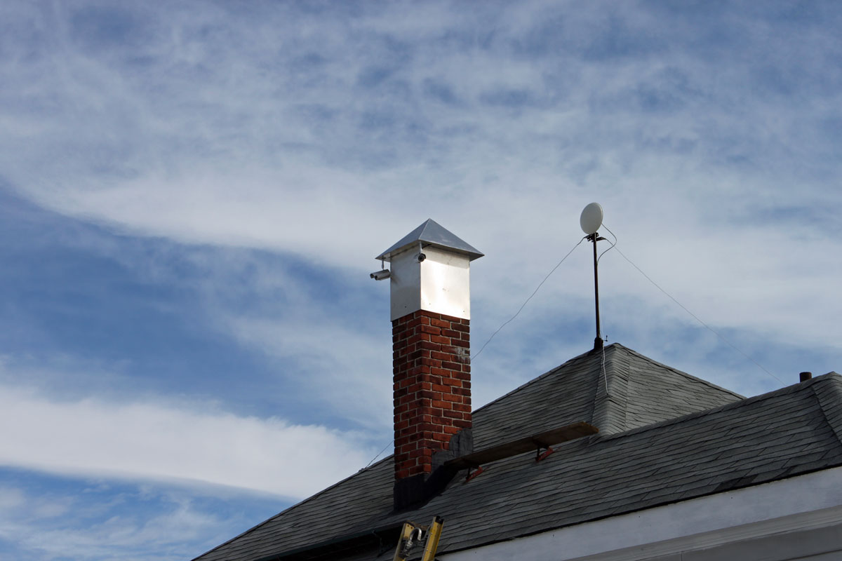
Transmitter site security cameras

Cameras mounted on old chimney platform.  This is the first set of cameras covering the south, north, and west approaches.  A fourth camera will be mounted on the back of the building covering the east approach.  Then, under the eves’ cameras will be mounted on all four corners of the building and the generator shed.  If anything moves, it will be recorded.
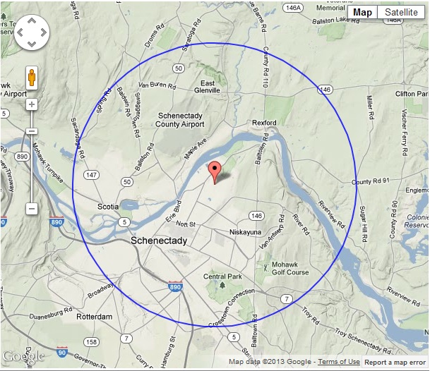
Nautel Radio Coverage Tool

This is a Webinar video from Nautel about their Radio Coverage Tool:

Highlights of the Nautel RF tool kit:

  • Analyze the proposed transmitter location’s coverage
  • Tower heights can be adjusted
  • Antenna gains can be changed
  • Transmitter power levels
  • Includes Terrain data
  • Includes population within coverage areas
  • Frequency Range 30 Mhz to 3GHz
  • Useful for general broadcast or point-to-point systems

This can be a useful tool for those looking to gauge the realistic coverage of a station in terrain-challenged areas.  It can also be useful for studying STL paths, RPU coverage, etc.

One problem is the power levels and antennas are preset, with the minimum setting of 200 watts into a two-bay antenna.  These settings are too high for use when investigating a potential LPFM.  For that, Radio Mobile Online (which is the engine behind the Nautel RF tool kit) can be accessed directly via www.ve2dbe.com/rmonline.html.  Requires an account, which is very easy to set up.  For most users, FM broadcast band frequencies will not be available, however, 2 meter amateur frequencies (146 MHz) are the default, and for all practical purposes, will model coverage in the FM band (88 to 108 MHz) just fine.

By creating a hypothetical LP100 transmitter site, the coverages between the FCC 60 dBu contour and the actual coverage based on terrain can be compared.  This is the FCC 60 dBu coverage contour:

Example contour, LP-100 station
Example 60 dBu contour, LP-100 station

According to the US Census data, this station has a population coverage of; 30,721 in the 70 dBu or 3.162 mV/m contour, 92,574  in the 60 dBu or 1 mV/m contour, and 165,183 in the 50 dBu or 0.316 mV/m contour. Courtesy of REC Network.  The 60 dBu contour is considered the protected area licensed for use by the FCC.

Looking at a coverage terrain map, the picture changes somewhat:

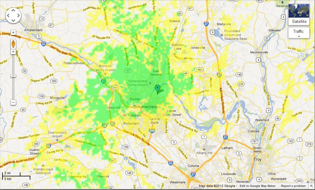
Example coverage map, LP-100 station

This is based on predicted receiver location using terrain data; receiver antenna height 1 meter, 90% reliability, minimum signal level 10 µV (20 dBu,  yellow, very good car radios) and 31.62 µV (30 dBu, green, good radios and indoor reception).  Areas to the south and east of the transmitter are shaded by a large hill, thus they show low or no signal on the terrain based coverage map.  UN Population data indicates the yellow has 178,573 and the green area has 72,014 persons.  This map does not take into account co-channel and adjacent channel interference, which there is sure to be.

When comparing the two maps, one can see the coverage holes in the terrain map that are within the 60 dBu contour.  There may also be a slight difference in populations covered because the FCC map uses 2010 US Census data and the Radio Mobile Map uses UN population data.  For general planning purposes, the area shaded in green would be a safe bet on good reception, all other things being equal.

Since the LPFM stations are very limited in their ERP, finding a good transmitter site that will cover the desired area will be key to a successful operation.

The Continental D323C medium wave transmitter

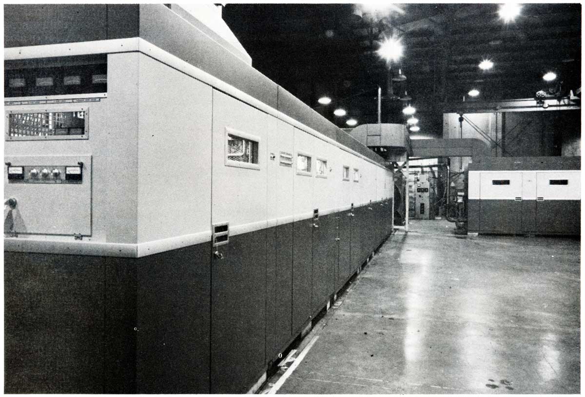
I found a 1981 Continental Electronics equipment catalog at an old transmitter site. These finds are great if one is interested in history and looking at the way things used to be done.  This particular transmitter is a 2,000 KW (2,000,000 watt) medium wave unit:

Continental Electronics D323C, Circa 1981

I believe most units like this were destined for use by government broadcasters in either the middle east or Western Europe.  I know there were several 1,000 KW medium wave stations in West Germany at one time.   The Continental transmitter is basically two 1,000 KW units (323C) combined.  They used a modified version of Doherty modulation, that is called “Screen and Impedance,” which accurately describes how it works.  More information from the Continental Catalog can be found here: Continental D323C.  The tubes (or valves depending on where you are located) used in the D323C were 4CW25000A tetrodes as modulators and IPA the final was a pair of X2159, which is an impressive tube.

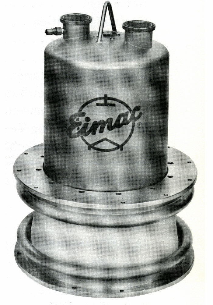
EIMAC X-2159 water cooled power tetrode
EIMAC X-2159 water-cooled power tetrode

The tube sat anode up.  The filament, grid, and screen connections are underneath.  Cooling water was pumped through the two connections on the top at about 130 gallons per minute depending on the plate dissipation.  With a 30° C rise, that equals about 96,000 BTU per minute.  The D323C had a dissipation of 400,000 watts for the carrier tube and 240,000 watts for the peak tube (640 KW total) under 100% modulation.  That equals about 2 million BTU per hour.  Notice the lifting hook, this tube weight in at 175 pounds.  Tube date sheet here.

Continental no longer makes medium wave transmitters, their closest high powered broadcast product now is the 418/419 and 420 HF (shortwave) transmitters.  The 420D does a wimpy 500 KW using a solid-state modulator section.

I remember in the early 1990’s when I was at the Harris plant in Quincy, they were working on a 1,000 KW solid state DX series AM transmitter for Saudi Arabia.  It had to be liquid cooled, which added another layer of complexity to an already complex system.

I don’t know if there is much call for 2 MW medium wave transmitters anymore as there are more efficient ways to reach remote populations and I can’t even imagine what the electric bill would be like.