Stereo Tool

FM and AM broadcast radio processing has gone through many iterations.  At first, the main processing function was to limit the input audio to a transmitter and prevent over-modulation.  This was a particular problem with early tube-type AM transmitters, where over-modulation could create power supply overloads and kill the carrier while engineers scrambled around resetting things and hopefully pressing various buttons to get the transmitter back on the air.

Over the years, processors incorporated not just limiting, but compression, gating, equalization, clipping, and so on all in an effort to keep ahead or at least abreast of the station across town.

Today, broadcast air chain processors come in all shapes and flavors.  In addition to that, internet streaming stations have their own unique set of issues to deal with.  The top-of-the-line Telos Omina or Orban Optomod systems are great, however, they can set one back a pretty large sum of money.  Enter then, the Stereo Tool PC based software processing program.
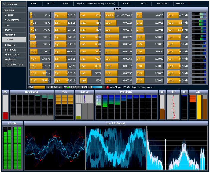
Stereo Tool sofware screen shot

The first difference between, say the Omina and Stereo Tool is the end user decides the hardware and basic operating system.  The second difference is Stereo Tool comes with a free trial.  Then there is the price difference, which ranges from about $48.00 US for the basic version, to $161.00 US for the basic FM version and finally $269.00 US for the full version (actual prices are in Euros, which will fluctuate day to day and the credit card company will likely charge an exchange fee).  Add to that a medium-speed (2 Ghz) Intel Pentium4 or better computer, 1 Gb or more of RAM, good sound card and it all comes out to a reasonably priced audio processor.

Here are some of the specific features for broadcasting:

  • Declipper
  • Hiss Removal Filter
  • FM Hiss Removal Filter
  • Automatic Gain Control (AGC)
  • 10-band multiband compressor / limiter / clipper
  • Phasing error (AZIMUTH) correction filter
  • Stereo booster
  • Bass booster
  • Final limiter
  • Distortion masking Loudness filter
  • Lowpass filter
  • FM pre-emphasis filter
  • FM stereo encoder
  • FM RDS encoder
  • Composite limiter

Much more info at the Stereo Tool website.

The idea of PC-based audio processing is new and interesting to most of us.  The designer and owner of Stereo Tool, Hans van Zutphen, was nice enough to answer a few questions I posed to him via email:

PT: What prompted you to write audio processing software?

HvZ: Since I was very little I’ve always wanted to have my own radio station. I remember playing with walkie-talkies and trying to receive their sound on a real radio when I was about 8 or 9. I never really did anything with it until I found out in 2001 that you could easily start a webradio station – I actually found out because I was listening to a pirate station in my car which turned out to have a stream; within a week my own station was online.

Of course, I needed a bit of processing for it, and I wrote some command line tools – a single band compressor, a stereo-to-mono converter that didn’t cause any loss of audio (I was broadcasting hard trance on a mono 56 kbit/s stream, and this was the only way to get a decent sound out of it), and sometime later a multiband compressor.

In 2004 I left the company I worked for (ASML, they make machines to make computer chips, customers are companies like Intel, AMD etc.) to start working for Philips Healthcare, where I was going to work on image processing for X-Ray systems. I had 2 months of ‘spare time’ between those jobs, and I wanted to learn to program in Visual C++, so I decided to a GUI around my command line tools, and make a Winamp plugin out of it. I called it ‘Radio Tool’. I never really planned to do anything with it, it was just an exercise project.

About a year later I came across the Winamp site again and I saw that you could upload plugins. So I uploaded my program, now renamed to ‘Stereo Tool’ because a Google search for “Radio Tool” gave far too many hits. Within a week there were over 1000 downloads and a while later it surpassed 90,000. At that point I decided to create a new version, Stereo Tool 2.0.

For quite a while this remained a hobby project, I occasionally worked on it for a few months and then I wouldn’t look at it for months. But at some point I was approached by someone people who worked at a “real” (FM) Dutch radio stations who asked for some extra features – he couldn’t get the audio loud enough, and that’s how I got into clipping. Things started to get better, I learned more and more about processing, the number of downloads increased and people became more and more enthusiastic about it. At some point, after reading something about how an FM stereo signal looks, I thought it might be possible to output a stereo signal with a 192 kHz sound card, so I bought one and did some tests and it worked that same night, and within a few weeks I added RDS.

PT: Do you know, approximately, how many stations (AM/FM/internet) Stereo Tool is being used on?

HvZ: FM: About 500, ranging from small community and pirate stations up to large nation-wide stations which run Stereo Tool at a dozen transmitter sites. Streaming: Not sure, but definitely over 1,000, probably a lot more.

PT: I have read through the forums on your site, Stereo Tool looks like a very complete processing system. Any plans for new features, future upgrades, etc?

HvZ: Yes. I’m currently working on a new multiband compressor. The multiband compressor in Stereo Tool is still based on the code that I wrote in 2001 for my webradio station, which in turn was based on an even older version that I had used on 8-bit audio. It also has far too many bands. Because of this, the multiband compressor is currently the weak spot of Stereo Tool. In the last weeks, I have made a new single-band compressor that sounds a lot better, it actually outperforms other compressors I have tested, and I expect great results for the new multiband compressor, which will also have fewer bands. Something else that I’ve been planning for a long time is a composite clipper, which will add 1-2 dB of extra loudness and especially better highs. Stereo Tool can already be louder with good audio quality than nearly any hardware box on the market (see for example this video, Radio 538 uses an Orban 8600 http://www.youtube.com/watch?v=4VpfcqUPQys – unfortunately due to the mpeg compression it’s a bit difficult to compare but listen for distortion ) – but there’s always room for improvement.

PT: What are the advantages of a PC software-based processor vs. a hardware-based (e.g. Omni or Optomod)?

HvZ: Ah, good question. Not sure if it’s the right question… With processing, a lot of things come down to taste, and there are several stations that have replaced their hardware processing with Stereo Tool not because it’s software and PC based but because they preferred the audio that comes out of it. Stereo Tool is also one of only 2 processors that contain a de clipper (the other one is the Omnia 9, I licensed my de clipper to them). For a demo of the declipper see: http://www.youtube.com/watch?v=oqOljvx9KaM

Also, Stereo Tool contains a stereo and RDS coder, but most other processors don’t, so instead of having a whole bunch of devices everything can be done in a single PC, which also results in better quality. Recently I added a new feature that enables synchronizing multiple FM transmitter signals that all connect to a simple Shoutcast stream (video: http://www.youtube.com/watch?v=GYQ5CYs0ZX8 ), so you also don’t need any streaming hardware anymore.

Of course, there’s the price. A hardware box that gives “similar” quality (of course every processor sounds different, and it’s a matter of taste, so it’s difficult to compare, but I’m assuming that things like low volume levels, gain riding, distortion, and lack of clarity in the highs are bad) easily costs $10,000 or more. And you can always easily upgrade to new versions. If you already have a PC with enough spare processing power you don’t need to buy anything.

I know that some people at radio stations are ‘afraid’ of using a PC in their processing path, but based on feedback I get from the stations that run my software it’s completely stable – and of course, if a PC does break, you can replace it with any fast enough PC you have lying around – you just need to put the proper sound card in.

But for development, the advantages are huge. If you use DSPs, it’s usually a lot of work to even make a very small change. When I worked at Philips Healthcare, the image processing that had been done – without many changes – on DSPs for many years was being converted to PCs because of the speed of development and the price of hardware. Once the conversion was finished, the development speed increased dramatically and 2 years later the image quality had improved beyond anything that was imaginable with DSPs. PCs get faster every year, and you don’t have to do anything for that – for the same price the processing power that you can buy roughly doubles every 1.5 years, and if you pay more you can get even more. If you use DSPs, you have to do a lot of work yourself, you cannot just ‘buy a faster DSP’. Testing things is very easy, I can write some code that does something new, post it on my forum and I’ll have feedback from users the next morning – with DSP that’s a LOT more difficult and it takes a lot more time. I’ve learned by now that everyone hears things in a different way, and occasionally there are groups of people who hear something they find very annoying while many other people (often including myself) don’t hear anything wrong with it at all. Especially in cases like this, it’s really great to be able to quickly send new versions to several people all around the world for testing.

PT: Are there any particular sound cards that work better with Stereo Tool?

HvZ: Yes. For the best results, use the Marian Trace Alpha, with the ESI Juli@ as the second-best choice (it needs calibration).

Thank you very much, Hans, for the interesting insight.

Check out the videos, especially the de clipper video, which is quite amazing.  That will clean up all but the most ham-handed DJ mistakes.

PC-based audio processing software is a great solution station on a limited budget that cannot afford high-end air chain processors.  There are many LPFM’s, Part 15 stations, and others that can get great-sounding audio and RDS for a very reasonable price.  Currently, the AM settings do not allow asymmetrical modulation, which is more of a US thing.  There is some talk of adding it in a later update.
Pinouts

Over the years, I have collected many pinouts for all sorts of interfaces, connectors, jacks, etc.  These are all stored on my laptop and on my smartphone.  It is easy enough to look these things up online, however, there are occasions when the internet is not available for whatever reason.  Thus, this is my collection of pinouts, many of which have been adapted from Wikipedia articles.  Many times I put things here for my own use.  However, if I have spent ten minutes looking for the USB pin out on my smartphone, someone else has done the same thing.  Most of these images have higher resolutions available.

Enjoy!

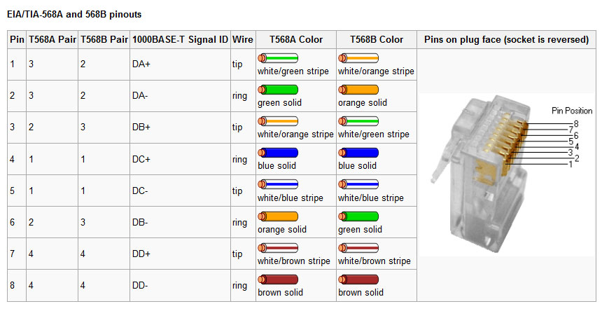
EIA/TIA 568a and b ethernet cable standard

Standard networking connectors for Ethernet connections. Rumor has it that only the “A” standard is accepted for government work and the “B” standard is being depreciated.

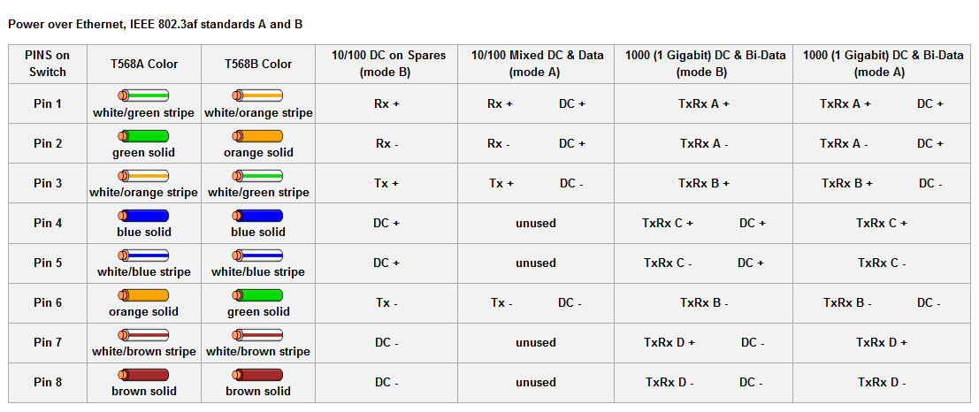
803.3af Power over Ethernet, imposed on EIA/TIA 568 a and b

Power over Ethernet pinouts. More and more commonly used in VOIP phone systems, but can also be found in wireless access points and other things of that nature.

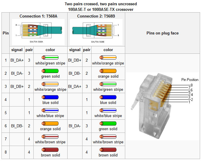
10/100 base T cross over cable
10/100 base T cross-over cable

Ethernet crossover cables are useful for connecting to similar pieces of equipment together, e.g. a computer to a computer, or a switch to a switch. Many new switches have port sensing, which will automatically cross the connection if a straight through cable is used.  Others have a specific port or a switch for a specific port which will cross over the cable.  Gigabit Ethernet uses all four pairs, thus a 1000 base T crossover looks a little bit different.

10/100/1000 base T Ethernet crossover cable

This type cable is backwards compatible with 10/100 base T systems.

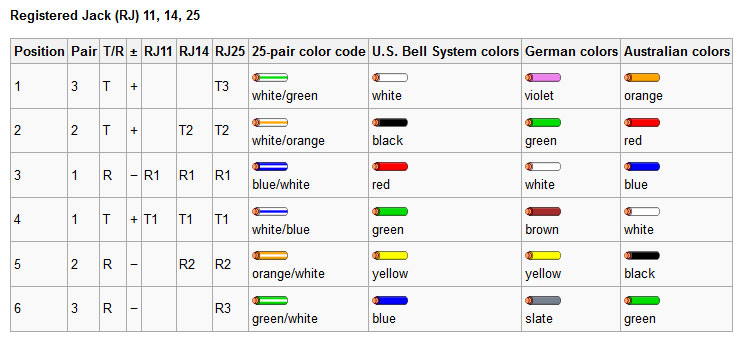
Registered Jack 11/14/25

Telephone system equipment jacks.

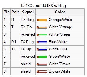
Registered Jack (RJ) 48, commonly used on T-1 and ISDN circuits

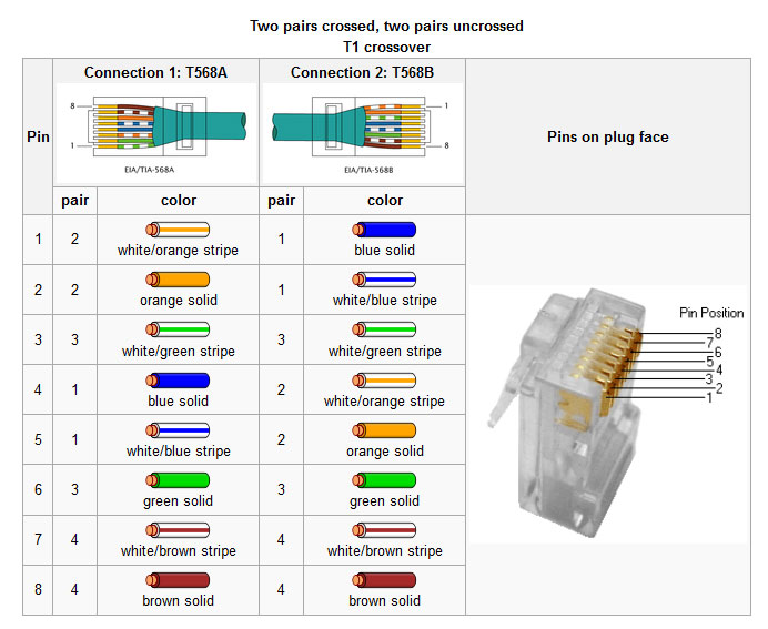
RJ48 and 48X used on T-1 (DS-1) and ISDN connections.  Since BRI and PRI ISDN are two wire circuits, the active pins are 4/5, which is the same as an RJ11.  I have often used RJ11 jacks for ISDN and found no issues with doing so.

T-1 (DS-1, DSX-1) crossover cable

Crossover cable for T-1 (DS-1 or DSX-1 interface). Note, this is different from an Ethernet crossover cable, which will not work for in a DS-1 interface.  A T-1 loopback connector goes from pin 1 to pin 4 and pin 2 to pin 5 on a 8P8C connector.

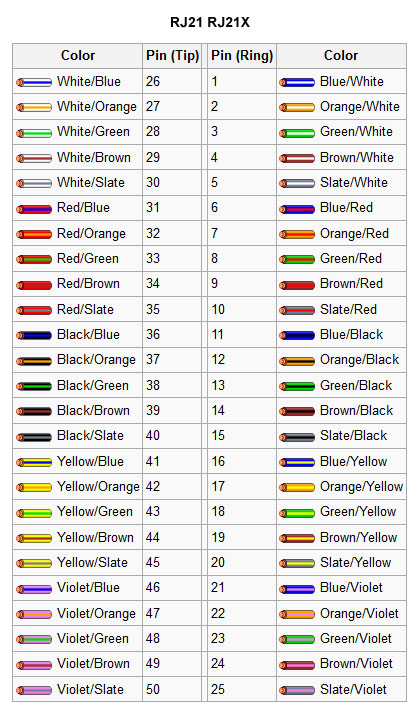
RJ21 and 21X color code.

RJ21 and 21X connectors are often found on the side of punch blocks and make for quick connections on cabling trunks.

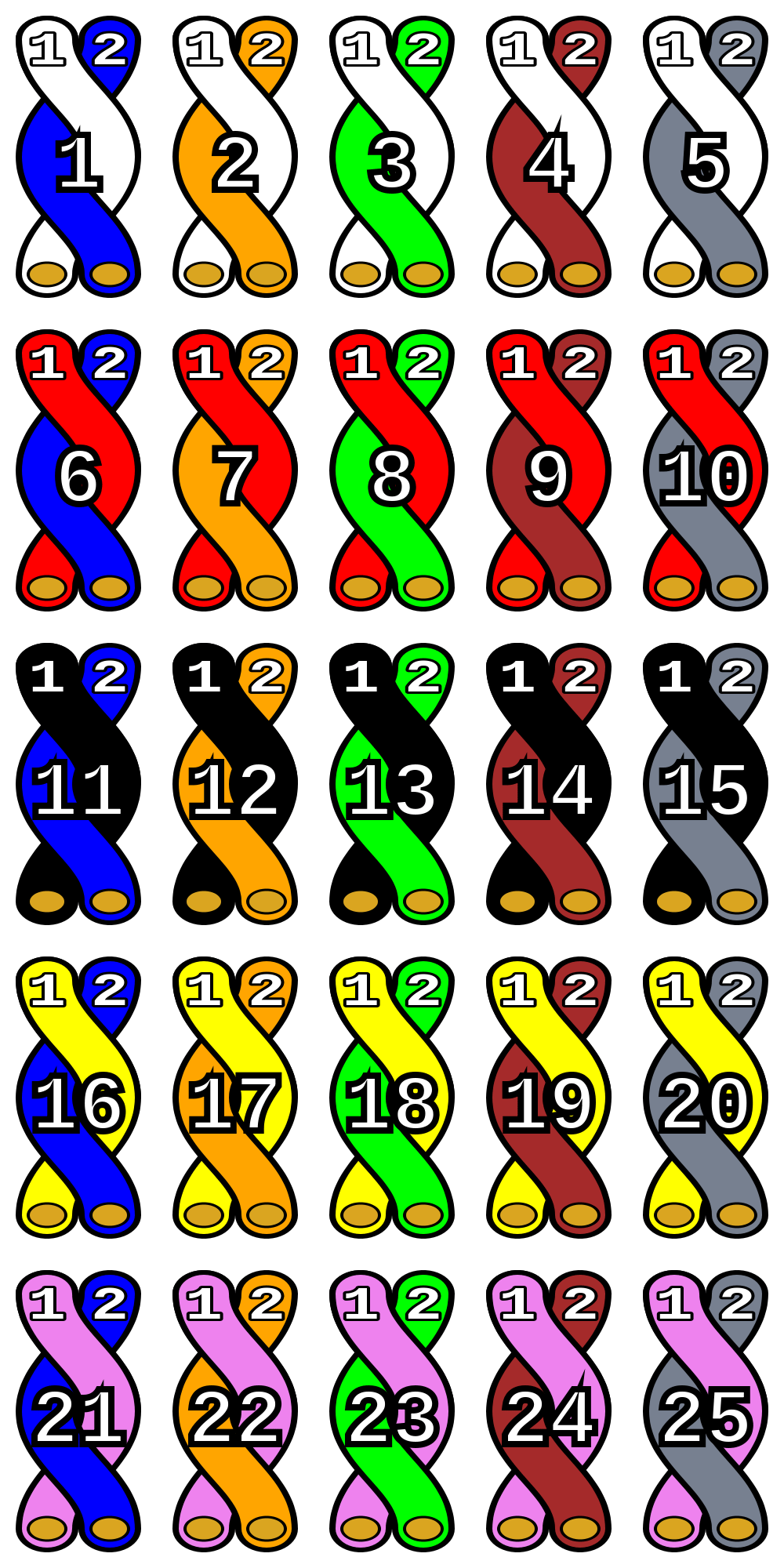
25 pair color code
25 pair color code

The generic 25 pair color code, which is always a good thing to have.

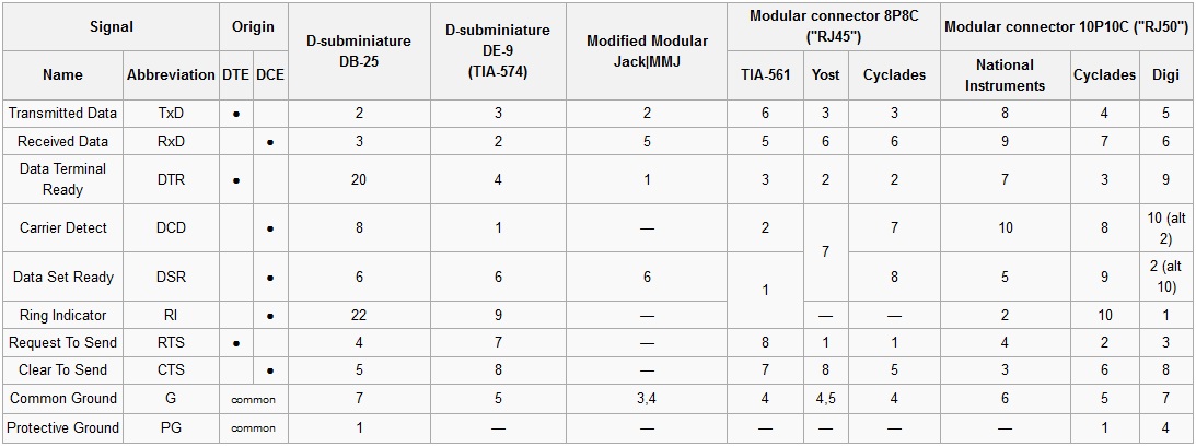
RS-232 data pins out for various connectors

RS-232 is still commonly used for data transfer in broadcast facilities. RS-485 is also used, however, that standard is often used with screw terminals or some other generic connection.

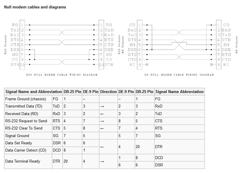
Null modems, cables and pinouts

Null modems for connecting equipment together and testing.

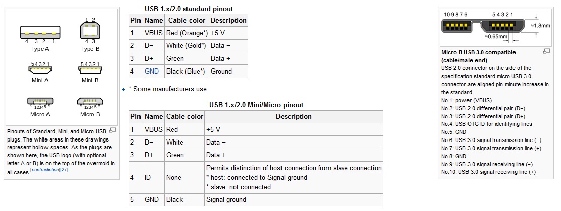
Universal Serial Buss (USB) connections and pinouts

Various USB connectors and pinouts. USB has replaced RS-232 data ports on most newer computers.

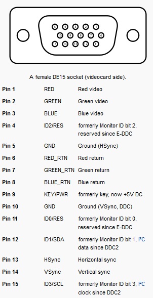
VGA connector and pinout

Computer graphics card pinouts.

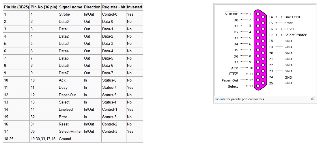
Computer Parallel port pinout

Computer parallel port pinout, not used very much anymore, replace by mostly USB devices. Can also be used as a limited GPI/GPO interface.  Some small automation software programs use pins 10,11,12,13 and 15 for closure information and pins 1, 14, 16, and 17 for output switching, machine starts and the like.

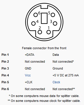
PS2 mouse and keyboard connector

PS2 mouse and keyboard connectors, again, replaced by USB but still found on older motherboards.

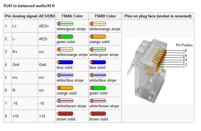
RJ-45 to balanced analog and digital audio

RJ-45 to balanced audio. This is a fairly standardized audio application for RJ-45 connectors developed by Radio Systems/Studio Hub. It is also used by Telos/Axia and Wheatstone, although often the +/- 15 VDC power is not included.

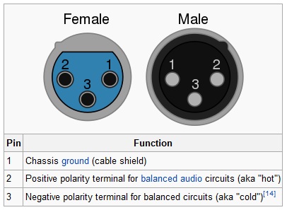
XLR connectors, old technology, still used

The ubiquitous XLR connector, still used for analog audio and also AES/EBU digital audio.

Goodbye you piece of junk

We are scrapping several old transmitters these last few weeks as part of a site upgrade  A couple of Harris FM20 and 10H transmitters are out the door.

Harris FM20H transmitter, circa 1970

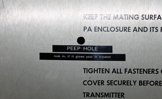
Some people like these transmitters. I am not one of those. I found that they were of dubious reliability, tended to drift out of tune and have AM noise problems, and had multiple catastrophic failure modes. If it was not tuned just right, it also had a tendency to have HF oscillations and internal arcing in the PA cabinet.

Harris FM20H3 PA cabinet modification

This transmitter had a non-factory authorized modification installed as a tuning aid.  Tune for best efficiency, and minimum AM noise then check and see if it is arcing.  It is also advisable to wear hearing protection during the tuning process.

Harris FM20H3, circa 1972

This particular transmitter was my nemesis for a couple of years. It is actually possible to hate an inanimate object, I can tell you. Goodbye, you piece of shit.

We tend to scrap these instead of dumpster them.  It saves the client a little bit of money on dumpster charges.  If all the metal is sorted out by category, e.g. all the copper windings are cut from the HV transformer and PS filter inductors, and all the brass, aluminum, and wiring harness are separated, then it is almost worth the time and effort.  Personally, I’d rather see all that material reused than landfilled.

Series surge suppressor

Radio facilities, particularly mountaintop transmitter sites, are prone to power transients. The causes can be varied, but most often, lightning is the culprit.  Long power transmission lines to the site are vulnerable to direct strikes and EMF-induced spikes from nearby strikes.  Other issues, such as switching transients, load fluctuations, and malfunctioning equipment can lead “clear weather” outages.  Of course, the best way to deal with such things is through prevention.

Power line surge suppressors have been around for quite some time.  They usually take the form of a MOV (Metal Oxide Varistor) connected between the hot leg and neutral or ground.  There are a few differences in designs, however.  Typically, most facilities employ a parallel surge suppressor.  That normally takes to form of an enclosure hung next to the main power panel with a group of MOV modules in it.  The MOVs are fed from a circuit breaker in the panel.  Like this:

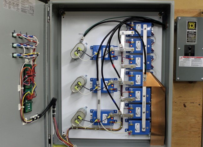
LEA parallel surge suppressor
LEA parallel or shunt surge suppressor

This is an LEA three-phase 208-volt shunt surge suppression unit, which has MOVs between all phases to ground and each other.  That is connected in parallel to the electrical service with the circuit breaker disconnect.  These function well enough, provided there is a good bit of series inductance before the unit and also, preferably after.  The series inductance can come from many sources, including long secondary leads from the utility company transformer or electrical conductors enclosed in metal conduit, particularly rigid (verses EMT, or FMC) metal conduit.  The inductance adds a bit of resistance to the transient voltages, which come in higher than 50 or 60 Hz AC waveform.

A better method of transient protection is the Series Surge Suppressor.  These units are installed in line with the incoming service and include an inductor to add the required series resistance coupled with MOVs and capacitors.  Most series surge suppressors also filter out harmonics and RF by design, something desirable, particularly at a transmitter site.  Series surge suppressors look like this:

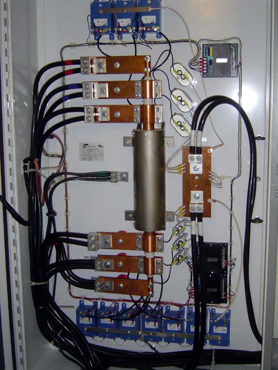
LEA DYNA systems series surge protector

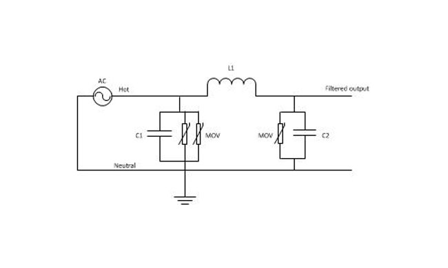
This is an LEA three-phase 240-volt unit.  As in the other example, all phases have MOVs to neutral and each other.   There are MOVs and capacitors on the line and load side of this unit (the line side is the bottom of the inductor).  A basic schematic looks like this:

Series surge suppressor basic schematic

A few things to note; MOVs have a short circuit failure mode and must be fused to protect the incoming line from shorts to the ground.  MOVs also deteriorate with age, the more they fire, the lower the breakdown voltage becomes.  Eventually, they will begin to conduct current at all times and heat up, thus they should also be thermally fused.  MOVs that are not properly protected from overcurrent or over-temperature conditions have the alarming capacity to explode and/or catch on fire.  From experience, this is something to be avoided.  Matched MOVs can be paralleled to increase current handling capacity.

The inductor is in the 100 µH range, which adds almost no inductive reactance at 60 Hz.  However, it becomes more resistive as the frequency goes up.  Most transients, especially lightning, happen at many times the 60 Hz fundamental frequency used in power distribution (50 Hz elsewhere unless airborne, then it may be 400 Hz).

Capacitors are in the 1-10 mF range and rated for 1 KV or greater as a safety factor.  The net effect of adding capacitance is to create a low-pass filter.  Hypothetically speaking, of course, playing around with the capacitance values may net a better lowpass filter.  For example, at 100 uH and 5 mF, the cutoff frequency is 225 Hz, or below the fourth harmonic.  Care must be taken not to affect or distort the 60 Hz waveform or all sorts of bad things will happen, especially to switching power supplies.

These units also need to have a bypass method installed.  If one of the MOV modules needs to be replaced, power to the unit has to be secured.  This can be done by connecting it to the AC mains before any generator transfer switch.  That way, the main power can be secured and the site can run on generator power while the maintenance on the surge suppression unit is taking place.