I am seeing more and more people getting into (or back into) vinyl recordings. This is somewhat heartening. My personal feeling is that good analog recordings offer a great way to enjoy music, particularly older music. The other nice thing; when I am holding a physical disk, it is mine. I bought it, I own it. No one can track it or delete it from my device.
Vinyl is actually Polyvinyl Chloride or PVC. Columbia records switched from Shellac record disks to PVC around 1947. According the the RIAA, vinyl sales peaked in the US around 1973. It is possible to find new vinyl in a few places like Target, Walmart and Barnes & Noble. There is a large market for used vinyl recordings in local record stores like Dark Side Records.
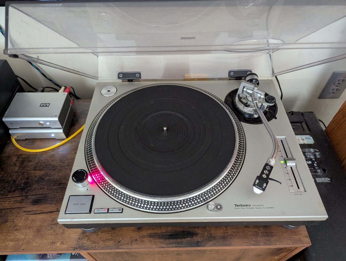
Many years ago, I retrieved this Technics SL-1200 Mk II turntable from the trash heap. This particular turntable had been through the flood after Hurricane Irene (2011). It spent more than 48 hours completely submerged in some pretty dank water. Following that, it went into the barn for many years without being looked at.
At some point in the last few years, I decided that I wanted a turn table for my Hi-Fi system. I retrieved the Technics unit from the barn and began the rehab. Fortunately, both the service manual and user manual are easy to find on line.
I disassembled the entire unit and inspected all of the parts. As it turned out, it was fresh water and the damage did not look too bad. There is some pitting on the under side of the platter and some general corrosion on the strobe dots. It took a while and a good deal of patience and elbow grease to clean everything off. The electronics in this turn table are only for control of the direct drive motor. Audio passes through to the outboard pre-amp. There is one 450 uF 50 VDC capacitor in the power supply which looked good, so I left it alone.
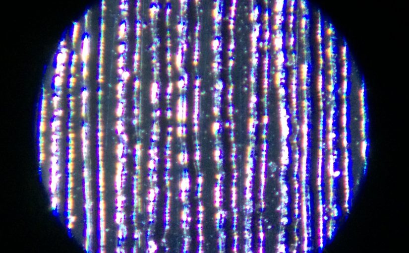
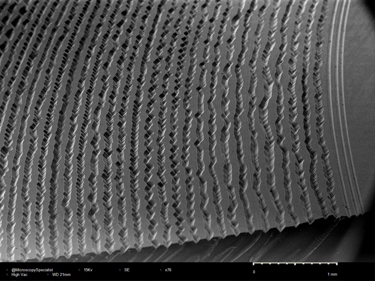
I put it all back together, but realized quickly that it needed to be set up correctly. There are many videos on Youtube that show how to align this particular model turntable. A complete alignment is important because the stylus must meet the grove at the correct depth and angle in order for the playback to be accurate.
The mechanical setup consists of five main things;
- The turn table must be completely level front to back and especially center post to stylus (the track of the tone arm)
- The height of the tone arm (stylus angle in the groove)
- The vertical tracking weight (proper frequency response, stylus and record wear)
- The anti-skating (proper pressure on both sides of the record groove, correct amplitude)
- Alignment of the cartridge in the cartridge head (stylus angle in the groove, proper left/right phasing, stereo separation and image)
These items are very easy to deal with on the SL-1200. It has feet that can be adjusted to level the unit. The leveling of the tone arm track is especially important to get right.
The height of the tone arm is set with the base arm ring. Some turntables do not have this adjustment, particularly consumer grade units. The tone arm should be level when the stylus is on the record.
The tracking weight is set by the tone arm balance weight. First, the tone arm is balanced so that it floats (in other words zero weight). The tracking weight depends on the cartridge and stylus being used. In this case, the cartridge is an Audio Technica AT-OC9XEN Moving Coil cartridge with an elliptical stylus. The tracking weight for that cartridge is 1.8 to 2.2 grams. I set mine to 2.0 grams.
Anti-skating is generally set for the same value as the tracking weight. However, this is sometimes too coarse. A test record with a blank band on it can help get this exact. It does not make a huge difference, but it is nice to confirm this anyway.
The alignment of the cartridge in the head shell is important, especially with an elliptical stylus. This is done using a Cartridge Alignment Protractor which can be downloaded for free from the vinylengine.com website
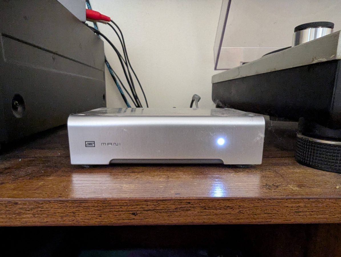
I purchased this piece of Schiit a few years ago to use with my vacuum tube amplifier. I have since switched to a Kenwood VR309 for my main listening setup. While the phone preamp in my Kenwood stereo is pretty good, I think this preamp sounds better, especially with the moving coil stylus.
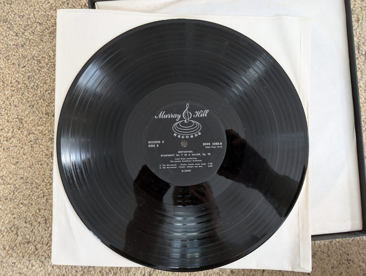
So, how does it sound? Pretty darn good. I dusted off some of my high school record collection and enjoyed explaining to my SO why a particular song was good. I also found a whole stash of like new Classical vinyl at the local Habitat for Humanity Restore, which was more to her liking. I love those places, you never know what you will find.