This is a neat piece of kit, designed to save those late-night/early morning callouts, which is the ultimate goal of all broadcast engineers, or at least it should be. This seems like a really good idea, however, BE has discontinued the product line, and the last manual update is from 2000.
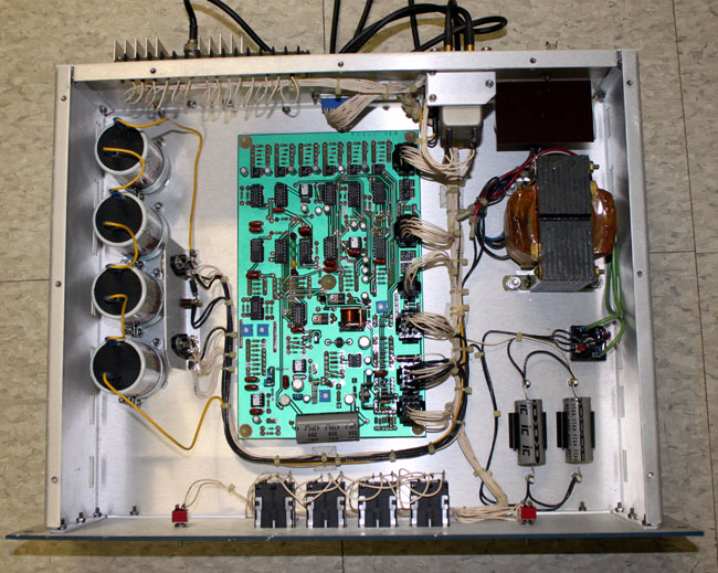
A small four-port coax switch is located next to the power supply transformer. This is controlled by the circuit board. The circuit board senses a loss of excitation by detecting a forward power level below the threshold set on the board. The power sample comes from the exciter forward power remote metering terminals. Thus, it can be used with any exciter(s) that have a remote forward power sample.
BE FW30 exciter switcher block diagram
The idea is to use the RF fault function output of the FX-30 (later FX-50) exciter to automatically switch from a faulted exciter to one that is working. Finally, it can be hooked to a remote control for manual switching. The unused exciter is muted and routed to a dummy load mounted on the back of the unit.
Broadcast Electronics FW-30 front, mid 1980’s BE blue
An alternate configuration would be to route the backup exciter to the backup transmitter instead of the dummy load. This would create the best redundancy on a limited equipment budget. It also has a battery bank designed to hold the last state of the unit through a power outage. As we have a good-sized UPS powering the remote control, STLs, and satellite receivers, the batteries are not needed.
On the face of it, a pretty good idea. I have had a few exciters fail over the years, which normally means the backup transmitter is placed in service by remote.
I did download the manual, but since it is currently listed on the BE website, it’s probably not a good idea to post the schematic. Suffice to say, it is a tad bit complicated what with all the CMOS logic and that. It is very possible to duplicate the functions of this equipment with a simple RF forward power sample and set a failure threshold with a comparator circuit. Hook that to a small four-port coax switch and a couple of RF mute/un-mute commands to each exciter and: Viola! Automatic exciter switching!
Not really a technical thing, but is something that I have to deal with as a self-employed contractor. The big change for me between being an employee versus someone who is self-employed is the amount of driving I do on a day-to-day basis. The group of engineers that I work with covers an area from New York City all the way up to the Canadian border. On any given day, I can be in Bridgeport CT, or Albany, NY or Burlington, VT, or White Plains, NY. The miles pile up quickly.
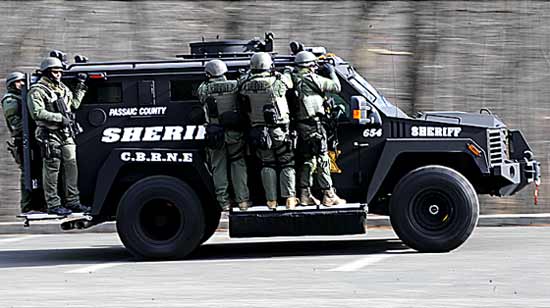
While out driving around, I get to see many new things. For example, yesterday I drove by the County Sheriff’s car:
County Sheriff’s Department armored vehicle, courtesy of NorthJersey.com
Something has changed, but I can’t quite put my finger on it.
The fact that I drive so many miles means that there will almost certainly be some interaction with local law enforcement, especially on that late-night trip to or from a transmitter site. As one State Trooper once put it, nothing good happens after 11 pm, which seemed to be enough to trigger reasonable suspicion and a traffic stop.
Of course, the police officers executing traffic stops are doing their jobs and the best course of action is to cooperate and maintain a polite, professional disposition. Usually, a traffic stop goes something like this:
While driving down the road, you notice a police car behind you. At some point, the lights will come on and you pull over, the police car pulls up behind you. At this point, you roll down the driver-side window, put the car in park (or neutral), and turn off the engine. Do not start rooting around for the registration, get out your wallet, unlatch your seat belt, or anything else, just sit there. The police officer will run your plate, which may take a few minutes. Then, after some period of time, he (or she) will get out of the police car and approach your vehicle on the driver’s side. When you see him approach, place both hands on the steering wheel, so that he (or she) can see them. The exchange will go something like this:
Police officer: Do you know why I pulled you over?
Yourself: No, I do not. (That is always the reply, even if you have a good idea why you were pulled over)
PO: You were (speeding, running a stop sign, red light or the general crossing road lines, unable to maintain lanes, unsafe lane change, etc) (fill in the blank).
Yourself: I was not aware of that.
From here, the interaction can take any number of routes; you may be able to explain what was going on, he may let you off with a warning, or you may get a ticket. As the driver, you will have to gauge the situation. Many times, I have found the best course is to explain that you are a radio (or TV) engineer on your way to or from some specific emergency somewhere. Many times, this will be enough, so long as the police officer does not suspect you of drinking or something similar.
Other times, the generic “you crossed the white (or yellow) line” will be used for a fishing expedition and he is looking for drunk driving, warrants, drugs, or something else to arrest you for. The most important thing to remember is not to give him that reason.
The police officer will ask you for your license and registration, he may ask you to step out of the car, take a field sobriety test, ask questions about items in the car, etc. Answer the specific question and no more, do not get chatty, volunteer information, etc.
If a traffic citation is issued, follow the directions, mail it in on time, and plead not guilty. Some form of trial will take place, often, before the proceeding, the prosecuting attorney or police officer will approach you and offer a plea to some lesser charge. To avoid wasting a lot of time on a trial, make the best deal possible and pay the fine.
On the other hand, if there is time to spare, go ahead with the trial. There are many ways to get out of a speeding ticket, especially if RADAR was used in the traffic stop. The law of sines is a good way to shoot holes in a police officer’s RADAR testimony. I like this one, because, in order for RADAR to be accurate, the measurement must be taken from dead ahead. Any angle to either side and the relative speed of the vehicle to the RADAR gun is reduced as a function of the sine of the angle. The greater the angle, the less the relative speed. Other things like calibration procedures (which can be checked), the last time the instrument was calibrated, the time interval between the use of the RADAR gun and passage of vehicle(s), did the police officer lose sight of your vehicle, etc.
I have gone to trial twice for speeding tickets, lost one because the system was rigged (this was on Guam), and won the other because the police officer lost sight of my vehicle while he turned around to catch me. That was on a back road, where there were multiple places to enter or exit the roadway and I was something like two miles away from the point of the infraction.
With any profession that requires a lot of driving, especially late at night, some interaction with local law enforcement will take place. Be polite, use common sense, be professional, don’t take any shit but don’t create any bigger problems either.
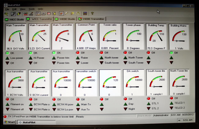
The old version of the software, that is. I like the graphical interface, just one glance is all that is needed:
Burk auto pilot
I have not had a chance to fool around with the newer version, the screen shots on the Burk website look a little bit different.
The setup and programming of macros is pretty easy; power/pattern change times, Pre-sunrise, and post-sunset functions, automatic tower light monitoring, AM Directional Antenna readings, and automatic transmitter restoration routines. If programmed correctly, the software can eliminate many of those late-night/early-morning phone calls, which is always a good goal.
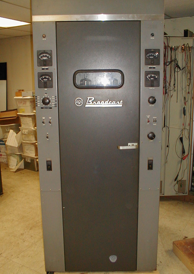
Other than a humming box, that is. RCA broadcast, prior to the period in the seventies just before they went out of business, made some good-looking transmitters:
RCA BTA-10U AM transmitter
The Art Deco design was favored for a number of years, especially with the AM units:
RCA BTA-1AR transmitter, circa 1960
Some of these RCA transmitters are still in service as backups.
GE made the BT-25A, which was a 50 KW transmitter in Syracuse, NY for a few years. These units were very similar to the RCA BTA-50 transmitters.
GE BT-25-A looking from the control cabinet
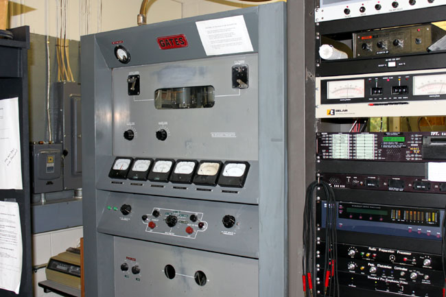
Gates of Parker Gates, pre-Harris, also made some classic transmitters:
Gates BC1J AM transmitter
I remember the BC5P had a similar look, with more transmitter cabinets.
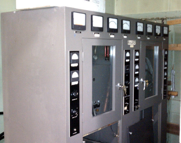
Bauer FB5000J AM transmitter
Fritz Bauer made a very solid AM transmitter. Good looking, too. We need more pictures of old transmitters and other hardware.