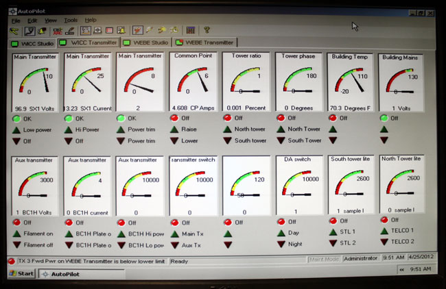
The old version of the software, that is. I like the graphical interface, just one glance is all that is needed:
Burk auto pilot
I have not had a chance to fool around with the newer version, the screen shots on the Burk website look a little bit different.
The setup and programming of macros is pretty easy; power/pattern change times, Pre-sunrise, and post-sunset functions, automatic tower light monitoring, AM Directional Antenna readings, and automatic transmitter restoration routines. If programmed correctly, the software can eliminate many of those late-night/early-morning phone calls, which is always a good goal.
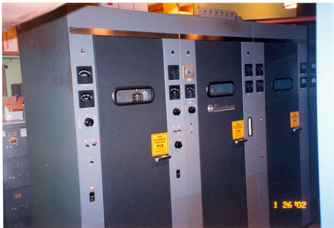
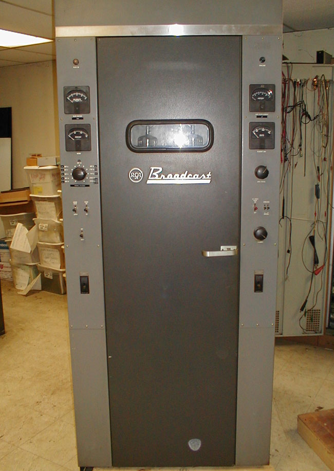
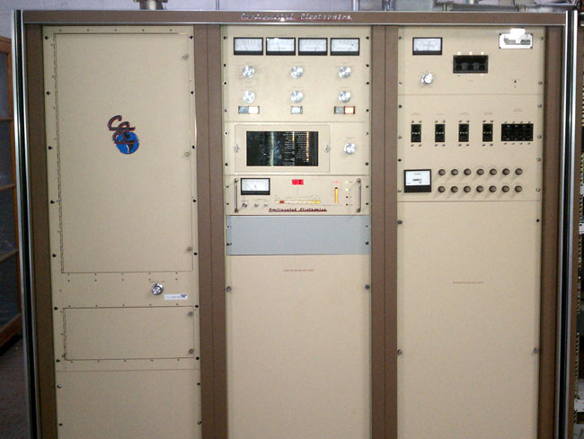
Other than a humming box, that is. RCA broadcast, prior to the period in the seventies just before they went out of business, made some good-looking transmitters:
RCA BTA-10U AM transmitter
The Art Deco design was favored for a number of years, especially with the AM units:
RCA BTA-1AR transmitter, circa 1960
Some of these RCA transmitters are still in service as backups.
GE made the BT-25A, which was a 50 KW transmitter in Syracuse, NY for a few years. These units were very similar to the RCA BTA-50 transmitters.
GE BT-25-A looking from the control cabinet
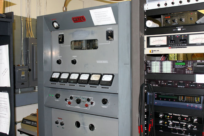
Gates of Parker Gates, pre-Harris, also made some classic transmitters:
Gates BC1J AM transmitter
I remember the BC5P had a similar look, with more transmitter cabinets.
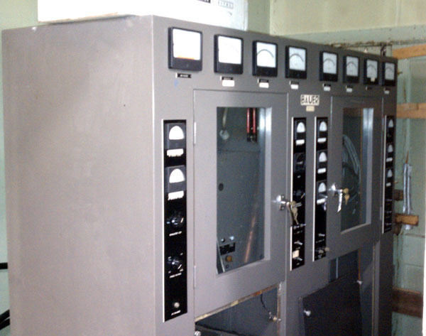
Bauer FB5000J AM transmitter
Fritz Bauer made a very solid AM transmitter. Good looking, too. We need more pictures of old transmitters and other hardware.
Good troubleshooters are becoming rare these days. To some, the idea of working through a problem, finding and then fixing an issue seems like a time-consuming, wasteful evolution. More often than not, it is easier to replace the entire assembly with a new one, throwing the old one away. This is especially true with computer components. The other option is to send a module or assembly back to the factory for repair. Truth be told, often that is a good course of action when a fully equipped repair bench is not available. Surface mount technology can be difficult to repair in the field, as can many RF components.
Being able to troubleshoot components and assemblies is still a valuable skill. Finding and identifying trouble is a good skill no matter what it is used for. I find analytical troubleshooting skills to be good life skills to have. I think my in-laws are occasionally amazed when I walk into a situation and point to something and say: There it is, fix that.
Coil burned out on 40 amp RF contactor
Many times, however, there is no smoking gun. Those situations require a bit of investigative work. The first step in troubleshooting is developing a history:
Has this failed before
Is there a history of failures
Has it been worked on recently
Is it new
Has it been installed properly
It is old
Has it been affected by some outside force like lightning or a power surge
This is where good maintenance records or maintenance logs come in handy. Recently, I have found many places that lack any type of maintenance documents, which means the repair history is unknown. This makes it difficult to find a good starting point and can greatly increase the amount of time required to troubleshoot a problem.
Once the pertinent history is gathered, it can be organized and analyzed for clues. For example, if something has been worked on recently, that is a good place to start. If something has a past history of failures, that is a good place to start. Newly installed equipment is subject to early failures under warranty due to component failures. Old equipment may just be plumb-worn out. Improperly installed equipment can exhibit all kinds of bizarre failure modes. That information coupled with known symptoms would indicate a good starting point for troubleshooting the problem.
If no good starting point can be discerned, then the next step is to recreate the failure. This usually means turning the thing back on to see what it does. Chances are good that whatever the problem is, it will still be there. Once a good set of symptoms have been identified, then it is time to start working at one end of the problem unit once the failed component is isolated.
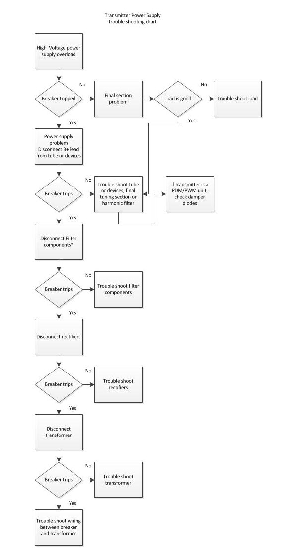
Oftentimes, equipment manuals will have troubleshooting guides. These can greatly speed up the process for large, complicated things like transmitters, generators, and so on. There is also the tried and true troubleshooting chart:
Generic transmitter power supply trouble shooting chart
This is an example of a troubleshooting chart for a transmitter power supply. Many equipment manuals will have this type of information in the maintenance sections.
It is also important to note that when working on high-voltage systems, it is necessary to have two persons on-site at all times.
Good troubleshooting skills have many applications.
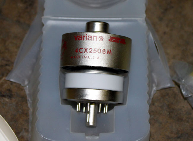
It’s a cute little thing. These were often used for driver tubes in FM broadcast transmitters. With the naming conventions of ceramic tubes, we can tell quite a bit about the unit without even looking at the datasheet.
The first number indicates the number of grids in the tube, 3 makes it a triode, 4 tetrode, and 5 pentode.
The C means it is a ceramic tube
The X indicates it is air cooled, a V is vapor cooled, W is water cooled, M is multiphase
The 250 is the plate dissipation is watts
B is the design revision.
Thus a 4CV100,000 is a vapor-cooled tube capable of dissipating 100,000 watts, something one might find in a high-powered MF or HF transmitter.
Other bits of critical information about tubes would be maximum plate voltage, maximum screen voltage, maximum grid voltage, maximum screen dissipation, maximum grid dissipation, and filament voltage. Something to keep in mind when tuning a transmitter.
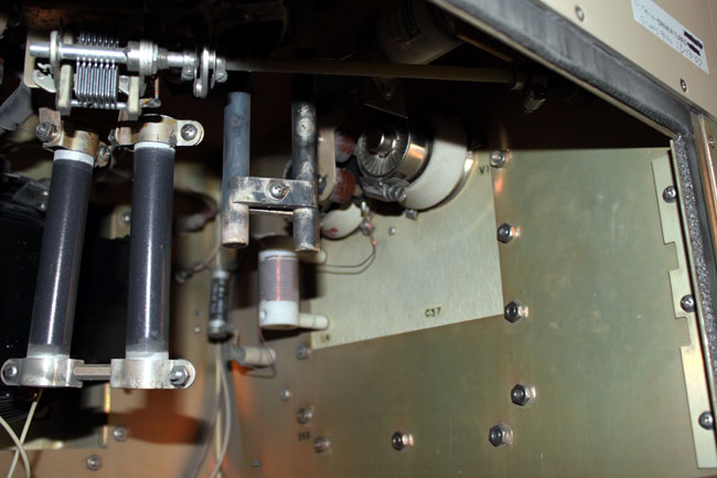
This particular tube is installed in the driver section of a Continental 816R2 transmitter.
Continental 816R2 driver section
I have noticed that these tubes have a much shorter life than there predecessors. Back ten or twenty years ago, they usually lasted 12-14 months. The latest set lasted only 8 months and both units failed catastrophically. That points to one of two things; either something in the transmitter has changed or something in the way the tubes are manufactured has changed. Once the new tubes were installed, I checked all of the parameters against previous maintenance logs. I also checked things like air flow, dirt and other possible culprits.
I could find no changes in the transmitter. The only thing I can think of is the fact that the tubes are installed horizontally, which causes the elements to warp and eventually break or short.
Continental 816R2 transmitter, WFLY, Troy, NY
I am thinking we may try to convert the driver section of this transmitter to a solid state unit. The transmitter itself is 24 years old, but is still works and sounds great. I’d hate to get rid of it because of its driver section.