The FCC reverses its former position on EAS text-to-speech, permitting stations to begin using it today (May 7, 2012). The FCC’s main issue with Text To Speech (TTS) was that it may not render the text accurate enough to be understood, especially in emergencies. This can lead to confusing messages and defeat the purpose of EAS altogether.
I have played around with some text-to-speech software and indeed it can mangle words, mispronounce punctuation as a part of the sentence structure, mumble, etc. Further, as I have said before, listening to some robo voice is very impersonal. But, I suppose that is the point, isn’t it; some big government agency computers generate messages that no one person is really responsible for. Bureaucratic paradise.
It is surprising to me how many times I have seen this done incorrectly in the field. Summing a stereo source, whether it is balanced or unbalanced is not simply twisting a couple of wires together. This will effectively reduce the impedance of the outputs by one-half. With newer, active balanced outputs, this may cause damage to the output amplifiers.
The parallel resistance formula is thus:
Therefore a 600-ohm stereo output tied together would look like this:
Rt = 1/(1/600+1/600) or 300 ohms.
It also creates an impedance mismatch with the next piece of gear, which will affect the common mode noise rejection of the circuit.
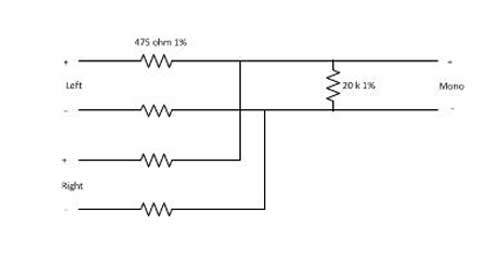
The best way to sum is through a resistive network. That way stereo separation is maintained, the impedance of the output circuits is maintained and the output amplifier will not current cycle. That looks like this:
resistive summing network
Pretty easy to fabricate in the field. It is good to do things the right way, it sounds better on the air too.
When they sold their Broadcast Equipment supply division to SCMS a few years ago, the handwriting was on the wall. Even so, it is a little surprising that they would exit broadcasting altogether.
The decision to divest in no way reflects the quality of the work Broadcast Communications performed in support of our customers and our company. Harris simply determined that Broadcast Communications could provide higher value and operate more effectively under a different ownership model.
They are spinning the broadcast division off to a new owner rather than completely shutting down the operation. In an e-mail received from Harris Morris, President of, Broadcast Communications Division, clients and customers will still receive support for existing products:
In the interim, Broadcast Communications will continue to be a part of Harris Corporation and operate business as usual. Our valued relationships, both longstanding and new, remain our top priority. The global Broadcast Communications team will continue to work diligently to ensure our commitment to our customers and partners remains steadfast, our execution to fulfill commitments is flawless, and our progress against strategic objectives remains focused.
Well, there you have it. This affects such things as Harris transmitters (AM, FM, TV, HF) and support, Harris consoles and studio furniture (previously Pacific Recorders and Engineering or Pacific Research and Engineering, AKA PR&E), and Intraplex STL systems, among others.
What does all this say about the future of terrestrial broadcasting?
This is a neat piece of kit, designed to save those late-night/early morning callouts, which is the ultimate goal of all broadcast engineers, or at least it should be. This seems like a really good idea, however, BE has discontinued the product line, and the last manual update is from 2000.
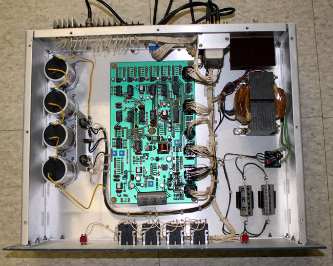
A small four-port coax switch is located next to the power supply transformer. This is controlled by the circuit board. The circuit board senses a loss of excitation by detecting a forward power level below the threshold set on the board. The power sample comes from the exciter forward power remote metering terminals. Thus, it can be used with any exciter(s) that have a remote forward power sample.
BE FW30 exciter switcher block diagram
The idea is to use the RF fault function output of the FX-30 (later FX-50) exciter to automatically switch from a faulted exciter to one that is working. Finally, it can be hooked to a remote control for manual switching. The unused exciter is muted and routed to a dummy load mounted on the back of the unit.
Broadcast Electronics FW-30 front, mid 1980’s BE blue
An alternate configuration would be to route the backup exciter to the backup transmitter instead of the dummy load. This would create the best redundancy on a limited equipment budget. It also has a battery bank designed to hold the last state of the unit through a power outage. As we have a good-sized UPS powering the remote control, STLs, and satellite receivers, the batteries are not needed.
On the face of it, a pretty good idea. I have had a few exciters fail over the years, which normally means the backup transmitter is placed in service by remote.
I did download the manual, but since it is currently listed on the BE website, it’s probably not a good idea to post the schematic. Suffice to say, it is a tad bit complicated what with all the CMOS logic and that. It is very possible to duplicate the functions of this equipment with a simple RF forward power sample and set a failure threshold with a comparator circuit. Hook that to a small four-port coax switch and a couple of RF mute/un-mute commands to each exciter and: Viola! Automatic exciter switching!