Backing up the UPS

Power loss is a critical failure, thus much money is spent to prevent or mitigate commercial power interruptions in broadcast facilities.  Backup generators and Uninterruptible Power Supplies (UPS) are the first lines of defense against commercial power interruptions.  It is prudent to research products and check reliability and interoperability when specifying and installing these systems.  However, even the best mechanical and electrical systems will fail, often at the worst possible time.  The UPS has a startling tendency to shut down, often at the worst possible moment, due to some internal control circuit or something similar.   This can happen when commercial power is being supplied without interruption.  The net result is some critical piece of equipment is now dark and the station is off the air.

Eaton Automatic Transfer Switch and UPS

There is a solution: The Eaton EATS EPDU TPC 2234-A Automatic Transfer Switch.

Eaton EATS EPDU
Eaton EATS EPDU

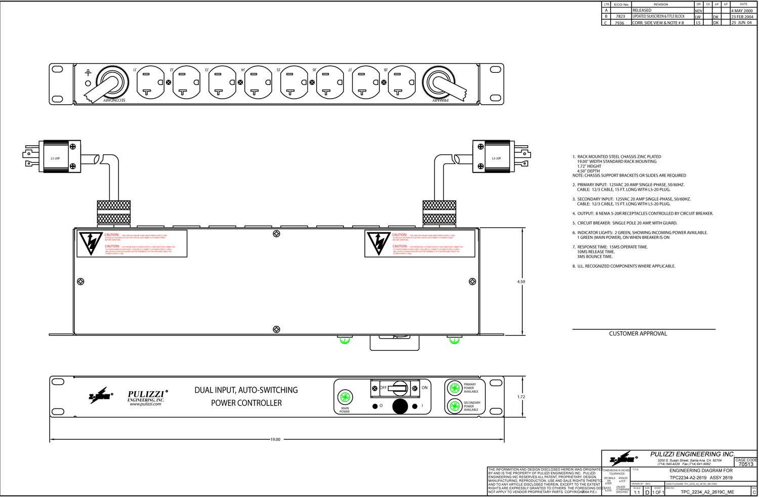
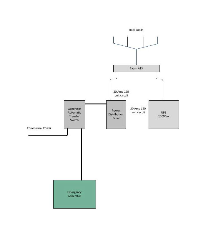
With this unit, the primary plug is connected to the output of the UPS, the secondary plug is connected to the commercial power source.  If the UPS fails, the load is automatically transferred to the commercial power.  Typically, the commercial power is also backup up with a generator.  The secondary plug can also be connected to a second UPS.  In theory, having two UPSs connected in parallel via an Automatic Transfer Switch would increase the Mean Time Between Failure (MTBF) by 50%.

UPS Eaton ATS EPDU block diagram

The Eaton products come with a variety of options, including basic network monitoring, advanced network monitoring, switching, and management.  Those features are available via Ethernet or serial data port.

Multiple layers of redundancy is the best method to avoid those late-night, weekend, or holiday phone calls.

WKZE transmitter site

We rebuilt this station’s studio couple of years ago.  WKZE is licensed to Salisbury, Connecticut.  The transmitter is located near Millerton, NY and the studio is in Red Hook, NY.  Today, I had to go to the transmitter site to fix a problem with the station’s processor.  While there, I snapped a few pictures:

WKZE, 98.1 MHz, Millerton, NY
WKZE, 98.1 MHz, tower near Millerton, NY

The WKZE single-bay antenna is mounted on the left-hand tower.

WKZE single bay Shively 6810 antenna
WKZE single bay Shively 6810 antenna with Radome

The transmitter is a CCA FM3000DS, made new in April, 1970:

WKZE 98.1 MHz CCA transmitter
WKZE 98.1 MHz CCA FM3000DS transmitter

The CCA designs are dirt simple. Grounded grid, driven with an external solid state amplifier that is a modification.

WKZE CCA transmitter, 42 years on
WKZE CCA FM3000DS  transmitter, 42 years on
WKZE CCA transmitter name plate

As you can see, this transmitter was originally manufactured for WHVW-FM, which is now WCZX.  The station has a large, mostly cult following throughout the mid Hudson valley.  Even though it is a 3,000-watt class A station, its coverage carries far beyond its theoretical 60 dBu contour:

WKZE predicted 60 dBu contour

This is because the station is in mono.

The Polyphaser IS-PT50HN-B

I found this on the floor at an old transmitter site:

Polyphaser IS-PT50HN-B DC block surge suppressor

Since it appears to be discarded, I ignored the dire warnings and opened it up to look inside:

Polyphaser IS-PT50HN-B DC block surge suppressor

This is is a DC blocked lightning surge suppressor designed for 890-980 MHz, 750 watts maximum.  The two parallel wires represent a capacitor, coupling the radio to the antenna, the inductor acts as an RF block to the gas discharge tubes.  The design is such that the inductor acts to block the normal in-use radio frequencies but will allow the 10-30 KHz lightning pulse to pass to the gas discharge tubes and thence to ground.  The inductor and gas discharge tubes are on the antenna side of the unit.  I measured these units with a DVM and they all appear to be good.

My only comment on this unit is that there is no effort to maintain the transmission line impedance.  At the upper end of the UHF spectrum, this can lead to return loss and wasted power.  For a receive application, it may not be so bad, but for a transmitter, I would rather use something else.

For lower VHF frequencies, something like this can be DIY fabricated with minimal expense and effort.  The case must be bonded to the station ground.

FM Fool website

Just for geeks, the FM Fool website is.  Nonetheless, it is a cool site to look at and can be used as a tool to find out what stations are available in any certain area.  Using the FCC database and terrain profile, it will print out a radar plot of all signals for any address in the US:

FM Fool Radar plot
FM Fool Radar plot

This plot is for my house based on a 30-foot outdoor antenna and includes all FM stations that are even marginally receivable.  We kind of live off to the side of nowhere.

The transmitter database was last updated on July 5, 2012.  Longer bars represent stronger signals.  Details about each transmitter are provided in the table to the right of the plot.

This is a companion site for the TV Fool website.  If you want to see what off-air TV signals are available at any given location, this is the way to do it.  A few years ago, I was thinking of getting rid of the Cable TV in favor of off-air reception.  Unfortunately, there are only a few off-air TV channels available at my house.  Therefore,  I threw out the TV.  Problem solved.