Update: Apparently this is quite interesting to a number of people. I have rescanned the manual, properly compressed it and which you may find it here.
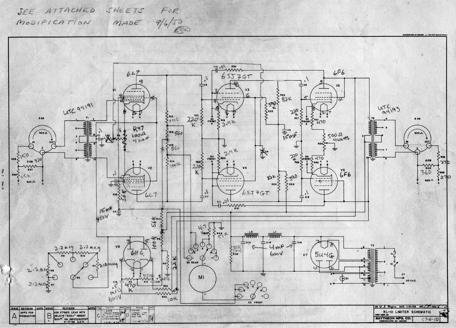
Found this manual at one of the older transmitter sites:
As this is an older design than either the Gates Sta level or the Collins 26U, it may not be as useful to tube audio enthusiasts.
Raytheon RL-10 Schematic diagram
The main issue with the Gates and Collins unit is the GE 6386 remote cutoff triode used, which were great tubes, but very difficult to come by these days. This design calls for a 1612 or 6L7, which is a pentagrid amplifier. Feedback is provided by the screen of the following stage, a 6SJ7GT. Anyway, perhaps it will give somebody some idea of how to make a good tube compressor limiter.
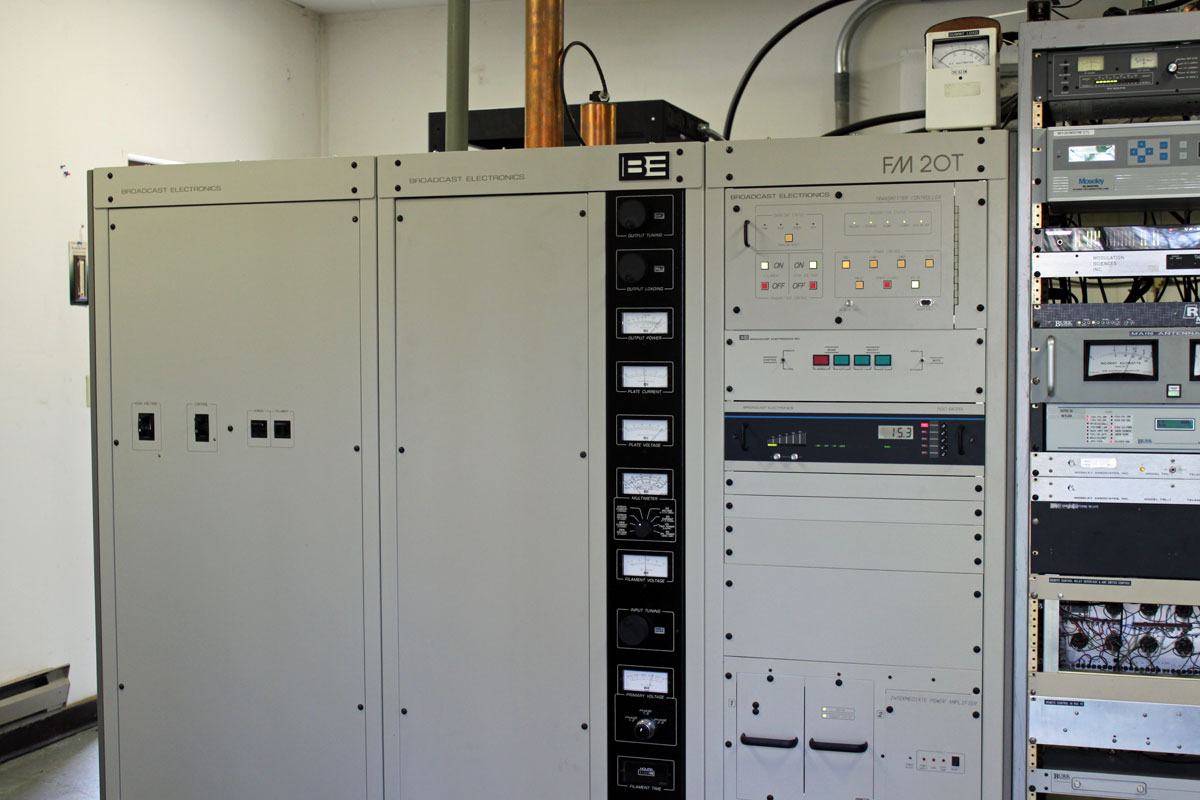
One of the stations that we do contract work for installed a Broadcast Electronics FM20T transmitter on June 6, 2001. It is still running on the original tube, a 4CX15,000A. By my calculations, that is 11 years, 7 months, and 9 days, or 101,712 hours.
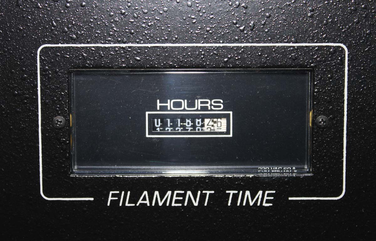
Broadcast Electronics FM20T transmitterBE FM20T filament meter
The hour meter shows 101,168 hours, which accounts for some maintenance, and other anomalies. Overall, the transmitter has a 99.5% up time. I do not think the transmitter suffered any failures, rather, things like the generator and the STL failed instead.
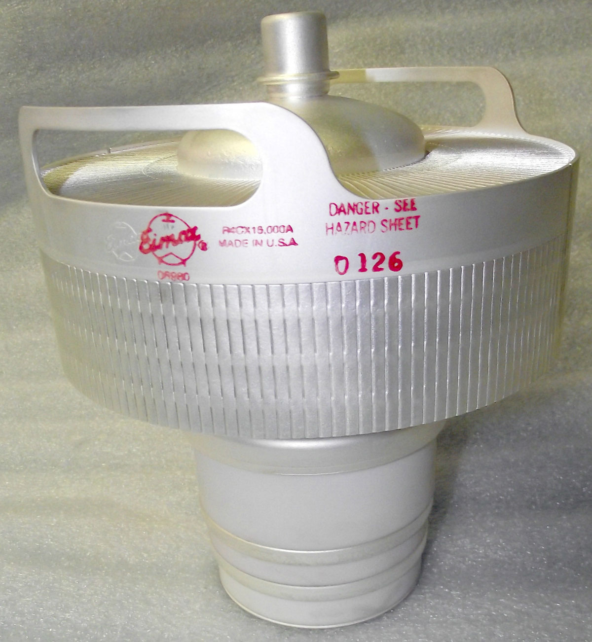
EIMAC 4CX12000A tetrode
Almost twelve years on one tube is pretty impressive. I know that other Broadcast Electronics T model FM transmitters have similar tube life expectancies. I wonder what Broadcast Electronics’ secret is.
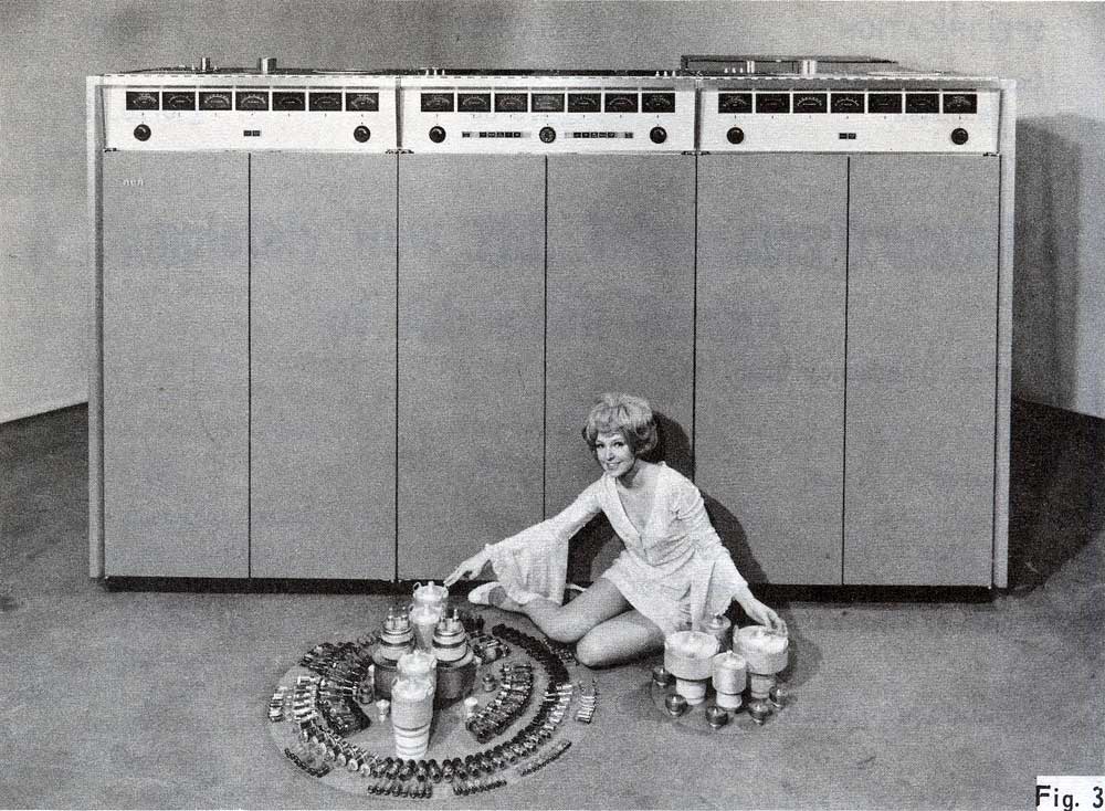
I found this promotional picture in an old NAB conference technical papers book dating to 1969:
RCA TT-30FL promotional picture
So here we see an obviously qualified and appropriately dressed technician gesturing to all the components she is about to install in the transmitter behind her. I wish I worked there. No, wait, I wish I had that transmitter and perhaps this fetching young woman would come and work at my station. Well, hell, I don’t need a TV transmitter, just the woman.
Sigh.
I wonder how many of these rigs RCA sold before the broadcast division went out of business.
By way of reference, the RCA TT-30FL is a VHF television transmitter, 30 KW peak visual power, 7.5 KW peak audio power, air-cooled.
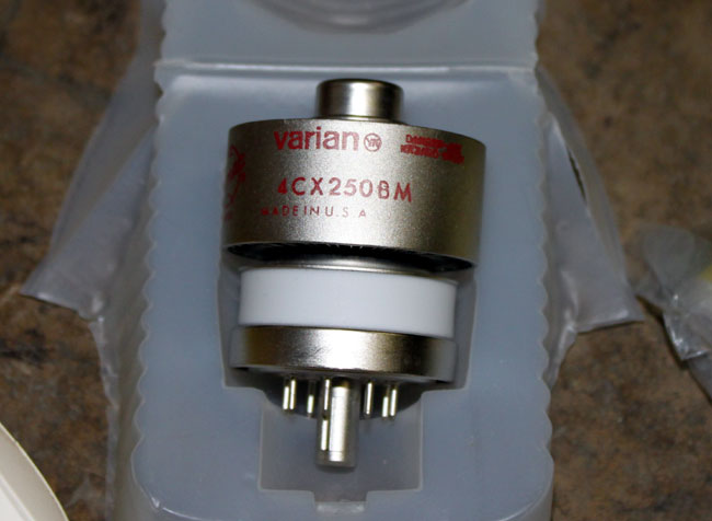
It’s a cute little thing. These were often used for driver tubes in FM broadcast transmitters. With the naming conventions of ceramic tubes, we can tell quite a bit about the unit without even looking at the datasheet.
The first number indicates the number of grids in the tube, 3 makes it a triode, 4 tetrode, and 5 pentode.
The C means it is a ceramic tube
The X indicates it is air cooled, a V is vapor cooled, W is water cooled, M is multiphase
The 250 is the plate dissipation is watts
B is the design revision.
Thus a 4CV100,000 is a vapor-cooled tube capable of dissipating 100,000 watts, something one might find in a high-powered MF or HF transmitter.
Other bits of critical information about tubes would be maximum plate voltage, maximum screen voltage, maximum grid voltage, maximum screen dissipation, maximum grid dissipation, and filament voltage. Something to keep in mind when tuning a transmitter.
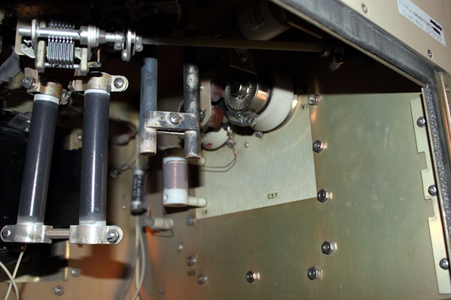
This particular tube is installed in the driver section of a Continental 816R2 transmitter.
Continental 816R2 driver section
I have noticed that these tubes have a much shorter life than there predecessors. Back ten or twenty years ago, they usually lasted 12-14 months. The latest set lasted only 8 months and both units failed catastrophically. That points to one of two things; either something in the transmitter has changed or something in the way the tubes are manufactured has changed. Once the new tubes were installed, I checked all of the parameters against previous maintenance logs. I also checked things like air flow, dirt and other possible culprits.
I could find no changes in the transmitter. The only thing I can think of is the fact that the tubes are installed horizontally, which causes the elements to warp and eventually break or short.
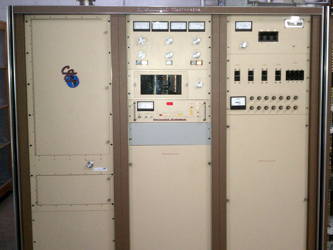
Continental 816R2 transmitter, WFLY, Troy, NY
I am thinking we may try to convert the driver section of this transmitter to a solid state unit. The transmitter itself is 24 years old, but is still works and sounds great. I’d hate to get rid of it because of its driver section.