The BE FM20T transmitter

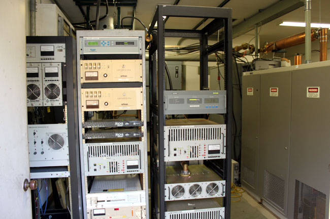
This is the main transmitter for WYJB in Albany, NY. The backup is the Harris FM20H3 on the right. I haven’t turned that unit on lately, but it normally makes quite a fuss the first time the Plate On button is pushed. The FM 20T on the other hand, is mellow and even-tempered.

WYJB 95.5 Mhz, class B, transmitter Albany, NY

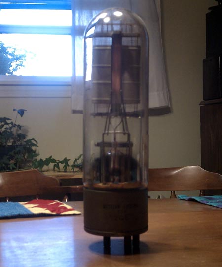
One other thing of note; The FM20T is still on its original tube.  I looked up the maintenance records for this transmitter, it was installed in December of 2000.  Eleven years later, the 4CX15000A (ed note; 4CX12000A) is still cranking out 15 KW TPO, which is impressive.  I found that high-power ceramic vacuum tubes actually seem to last longer when run closer to their limits than those that are running at half power.

Judicious management of filament voltage is required to achieve this type of longevity.  There is a set procedure for installing a large ceramic vacuum tube:

  1. After the tube is in the transmitter, run it at a full filament voltage for at least an hour or so before turning on the plate voltage.  This allows the getter to absorb any stray gases in the tube.
  2. Once the plate voltage is applied, proper tuning should be completed as quickly as possible.  Tuning procedures vary from transmitter to transmitter, however, the general idea is to obtain the maximum power output for the least amount of plate current while keeping the PA bandwidth within acceptable limits.  Some transmitters can get narrow-banded at high efficiencies, which manifests itself as higher AM noise.
  3. After the tube has been in use for 90-100 hours, the filament voltage should be reduced gradually until a drop in the transmitter output power is noticed, then increased by 0.1 volts.

This maximizes the filament life for that particular transmitter and power output.  Once the filament can no longer boil off enough electrons, the tube power output drops and it is time to replace it.

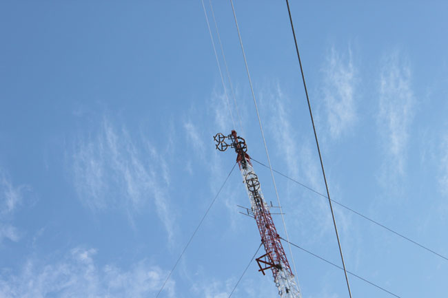
This site also has two other radio stations, WZMR, 104.9  and WAJZ 96.3 , both class A using solid-state transmitters of less than 1,000 watts:

WAJZ and WZMR Energy Onix solid state transmitters
WAJZ and WZMR Energy Onix solid-state transmitters

Not the prettiest sight in the world, but it does stay on the air.  There is no money to go back and neaten up this work, unfortunately.

The tower supports all three antennas.  There was some discussion of a common antenna for all three stations, however, WZMR is a directional station, thus it would require its own antenna.  Doing a common antenna for the other two stations was cost prohibitive, so the tower supports three two bay antennas.

WYJB, WZMR, WAJZ FM antennas, New Scotland, NY

The stations are all located in the New Scotland, NY tower farm.  WYJB is licensed to Albany, WZMR is licensed to Altamont and WAJZ is licensed to Voorheesville.

RCA receiving tube manual, 1964 edition

RCA receiving tube manual

I found this in the great clean out of 2010, Bridgeport, Connecticut.  Once upon a time, I had a slightly newer version of this, I think from 1972 or so.  This version is from 1964 and gives a complete rundown of most small tubes that were manufactured back then.

There is something about a well-designed, well-maintained piece of tube gear.  I remember an old Collins tube console that was in a production room at a small AM station.  The console went dead (the paper clip shorted the B+) and I fixed it.

I recall listening to the test recording of my own voice from a reel-to-reel machine when I fixed the console.  It sounded better than I’d ever heard it, not that I have a great radio voice, by any means.

A tube is a voltage amplifier versus a transistor, which is a current amplifier.  A tube does not have the same fidelity as a transistor, as the voltage reaches its peak, it gets a little fuzzy, adding some distortion and harmonics.  Tube gear adds warmth, what a musician might call Timbre. The combination of fundamental frequency and varying amplitudes of harmonic frequencies allow a listener to tell the difference between a piano and a guitar playing the same note.

This is what the current crop of tube mic preamps and other tube products tries to reproduce.  Several companies have come out with an amplifier design that has mostly transistors and one tube, usually a 12AX7.    Unfortunately, at least in my opinion, they fall a little short.  If you want to have the “tube sound,” it needs to be all hollow state.

What is intriguing to me are the schematic diagrams in the back of the book.  There is one for an audio amplifier:

RCA receiving tube manual audio amp schematic diagram C 1964
RCA receiving tube manual audio amp schematic diagram, C 1964

This is a single-channel unit, for stereo, it would need to be duplicated.  Also, I would lose the tube rectifier in favor of a solid-state full wave bridge, which would simplify T2 somewhat.  The OA2 could also be changed to a diode.  Looks like unbalanced audio, which could be modified with an input transformer.

Another interesting diagram is this one, which can be used as a mic preamp:

Microphone Preamp schematic diagram RCA receiving tube manual C 1964
Microphone Preamp schematic diagram RCA receiving tube manual C 196

That looks like a pretty solid design, a few tweaks here or there to add some gain reduction and some type of output level adjustment and I would be a really cool piece of gear.  Again, the tube rectifier could be replaced with something solid state.  The output transformer would likely have to be changed to something like 600 ohms.

Couple that to something like this, the Collins 26U compressor/limiter, and one would have a great sounding microphone processor:

Collins 26U compressor limiter

Looks pretty cool.  R10 is used to balance the two plate currents.  I would be interested in the transformer values, input/output impedances, voltages, etc.  The 6386 tube is very hard to find these days, a good substitute would be a 5670 which is still made by several manufacturers.

Update:  This is a picture of a Collins 26-U sitting on my boss’s floor.

Collins 26-U compressor limiter

A great online source for tube information is Electron Tube Data Sheets.

If I have some time this winter, it may be a fun project to fool around with.

Western Electric 212E vacuum tube

The company I work for is in the midst of cleaning out a studio location.  Most radio engineers are some form of pack rat.  I know I have been guilty of this myself, not wanting to throw something away because tomorrow, it might be needed.  That was carried out to the extreme at this location.  One of the things that I found in my clean-out was a Western Electric 212E vacuum tube.

Western Electric 212E vacuum tube

It is an impressive thing, measures about 12 1/2 inches tall, including the pins.  I am thinking this is pretty old, it probably came from a pre-WWII Western Electric AM transmitter.  This would make the most sense, as the station signed on in 1926 with 250 watts.  Back in the day,  Western Electric was the patent holder for AM technology.   In fact, there was some talk of suing General Electric for patent infringement after the airing of the world series by WJZ and WGY in 1922.  Parent company AT&T was working on radio modulation techniques to implement with their telephone system.

These tubes were used for audio amplification, according to the spec sheet, the plate could dissipate 275 watts.  Filament voltages is 14 volts at 6.2 amps, the plate voltage was 3,000 volts, maximum.  It is a tetrode.  The RF counterpart to this tube is the WE 308A.

From what I am to understand, these have not been made since 1960 or so.   I also understand there is quite a cult following for this tube amongst Asian audiophiles.  There are several examples of extremely low distortion class A and AB amplifiers using this tube type.  Some prices on eBay are in the $1,500 to $2,000 per tube range.  Unfortunately, I don’t think this one works anymore as there is a loose screw and little bits of what looks like control grid wire in the bottom of it.  It does light up with 12 volts on the filament, however.

Rebuilt tubes

As broadcasters, we don’t really hear that much about ceramic power vacuum tubes these days, as more and more broadcast transmitters migrate to solid-state devices.  Once upon a time, however, power tubes were the engine that drove the entire operation.  Tubes had to be budgeted for, stocked, rotated, and replaced on a regular schedule.  Some of those dern things were expensive too.

Take the 4CX35,000A which was used in the Harris MW50 transmitters.  The transmitter used two of these tubes, one in the RF section and one in the modulator.  As I recall, new tubes cost somewhere north of $8,000.00 each from EIMAC.  Plus, in the A models, there were two 4CX1500A driver tubes.  All of which could add up to an expensive maintenance cost every two years or so.

The next best option was to buy rebuilt tubes.  Rebuilt tubes were about half the cost of brand-new ones.  Some people complain that rebuilds don’t last as long, or only last half as long as the new tubes.  I never found that to be the case.  I often found other factors that affected tube life far greater, such as filament voltage management, cooling, and by extension, cleanliness.

I can say I never had a warranty issue with ECONCO tubes.  I cannot say that about EIMAC, as during the late 90s and early ’00s (or whatever you call that decade), I had several brand new 4CX3500 tubes that were bad right out of the box.  These days, ECONCO and EIMAC are both owned by CPI.

I spoke with John Canevari from ECONCO who had a lot of information.  For example, as the tube ages, the filament gets more flexible, not less.  Most ceramic power tubes use a carbonized tungsten filament containing some small amount of thorium.  As the tube ages, the filament can no longer boil off enough electrons and the emission begins to drop off.  That is the normal end of life for a power tube.  Occasionally, some catastrophic failure will occur.

There are many steps in the rebuilding process:

  1. Dud is received from the field, the serial number is recorded and the tube is tested in.
  2. The tube is prepped by sand-blasting the sealing rings
  3. It is opened
  4. The filament is replaced.  In 60-70% of the cases, the grid is replaced.  In those tubes that have a screen assembly, 20-60% of those will be replaced.
  5. The Interior of the tube is cleaned
  6. The tube is resealed and tested for leaks with a gas spectrometer
  7. The tube is placed on the vacuum machine.  Tubes are evacuated hot, smaller tubes take 12 to 24 hours, and very large tubes can take up to one week.
  8. The tube is nipped off of the vacuum while still hot.  When the tube is fully cooled the vacuum scale is normally around 10-12
  9. The exterior of the tube is cleaned and replated.  Silver for tubes that are socketed and Nickel for tubes that have leads.
  10. The tube is retested to the manufacturer’s original specification or greater.

After that, the tube is sent back to its owner or returned to stock.  John mentioned that they are very proud of their vacuum tube processing machines, so I asked if he could send along a picture.  They certainly look impressive to me, too:

vacuum tube processing machine
Vacuum tube processing machine, photo courtesy of ECONCO

Not exactly sure which tube type these are, but they sure look like 4CX15,000:

vacuum pump on rebuilt ceramic power tubes
Vacuum pump working on rebuilt ceramic power tubes, photo courtesy ECONCO

Econco has been in business since 1968 and rebuilds about 600-1,000 tubes per month.  In the past, broadcasters used most of the larger tube types.  However, with the majority of broadcast transmitters shifting to solid state, other markets have opened up such as industrial heating, military, research and medical equipment.