Zonecasting; the Technical Details

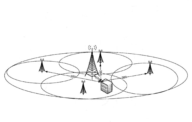
I saw this item many weeks ago, but, had not had time to look at it until now.  Geo Broadcasting Solutions has filed Petition for Rule Making (RM-11659) based on a system that divides the coverage area of major stations into smaller zones allowing for ad targeting of specific audiences.  They have coined the term “Zone Casting” to describe the scheme. It is covered by two US-issued patents filed by Lazer Spots, LLC: 20120014370 and 20110065377.  After a look at these two patents, it seems there are three possible ways to accomplish this Zone Casting Scheme:

  1. In the first described method, the main transmitter is broadcasting area wide and all the zone transmitters are muted.  An inaudible signal is transmitted to all units, the main transmitter is then muted and the zone transmitters turn on and transmit localized content.  After the local information is transmitted, the zone transmitters mute and the main transmitter resumes broadcasting.
  2. In the second described method, the main transmitter and the zone transmitters are broadcasting area-wide information.  The main transmitter ceases broadcasting area-wide information and the zone transmitters begin broadcasting localized information.  At the end of the localized information, the main transmitter and zone transmitters transmit area-wide information.
  3. In the third describe method, the main transmitter and zone transmitters are broadcasting wide area information with “capture ratio pattern.”  The main transmitter initiates an alteration, temporarily becoming a zone transmitter.  The zone transmitters then transmit localized content.  After the localized content, the main transmitter becomes a main transmitter again.

All of the transmitters are linked to the studio via digital STL systems, and content for the zone transmitters is distributed via IP network.  The transmitter frequencies are synced with GPS, similar to FM on channel booster stations.  Method number three includes possibly switching the transmitter output to a lower gain and or lower height antenna.

Zone Broadcasting Conceptual Diagram

Of the three methods, the first system will result in the fewest interference issues.  No matter which method is used, there will be interference issues between the zone transmitters and or the main transmitter where the signal strengths are equal and the audio is 180 degrees out of phase.  These can be moved around slightly by adding delay to the audio signal, but they will always be present.  More about Same Frequency Networks (SFN) and Synchronized FM signals can be found here.  While the zone transmitters are transmitting dissimilar localized information, standard capture effect rules apply.

The system has had limited testing in Salt Lake City, Utah (KDUT) and Avon Park, Florida (WWOJ), which according to the filing and comments, went well.

Geo-Broadcasting is applying to conduct a full test with WRMF in Palm Beach, FL.  The expected installation will include up to 22 zone transmitters.

Conceptually, tightly targeted advertising is not a bad idea.  Advertisers like it because they perceive a better return for their dollar.  The cost of such a system is not insignificant. Transmitter site leases run $1-2K per month, leased data lines, equipment, installation work, equipment shelters, etc will likely run several hundred thousand dollars or more.

If it gets approved by the FCC, it will be interesting to see how it works and whether or not the system is financially justifiable.

North East Commercial Radio Antennas and Towers

NECRAT logo
NECRAT logo

Or NECRAT for those who have been around the internet for a while. Many, if not most of you will know Mike Fitzpatrick’s NECRAT website which features many pictures of radio transmitter sites around the country (not just the Northeast).

Even before I began blogging, I checked NECRAT often for interesting pictures of many different transmitter sites.

If you are one of the few who has not visited his site, go and check it out: http://www.necrat.us

Tower light malfunction

We were notified that the WFAS-AM tower lights were out, thus, it was time to investigate. This problem was easy to find. Upon removing the waterproof cover on the tower light flasher box, I found this:

SSAC melted tower light flasher, damaged by lightning
melted SSAC B-KON tower light flasher, damaged by lightning

As soon as loosened the screws on the cover, I smelled the unmistakable odor of burned electronics and plastic.   I disconnected the flasher and covered the photocell, which turned the side markers on.  Of course, the top flashing beacon was dark, therefore, it was time to report the outage to the FAA.  The nationwide number to report tower light outages is (877) 487-6867.  That number is for an automated system, however, eventually, it leads to a live person.  Since the new reporting system was established, the only required information is the tower ASRN.  From that information, the operator will access a database and have all the required information to issue a NOTAM.  In the past, many questions were usually asked; what is the nearest airport, how far away is the airport, how tall is the obstruction, what is the position, etc?  Therefore, things have become slightly easier than before.

Once the outage is reported and a NOTAM is issued, the tower owner generally has fifteen days to correct the problem.

So, you call this work?

A trip to the WSPK transmitter site on a pleasant day, or, one could say, another day at the “office.”  Tower painting season is here, I’ll post some more about that later.  This is a nice set of pictures from the top of Mt. Beacon, in Beacon, NY.

Hudson Valley looking north from Mt. Beacon

South Mount  Beacon with the old fire tower:

Mount Beacon looking south at the old fire tower

Tower farm; two TV stations, Media Flow, one radio station, three translators, several cell carriers, one paging company, some government two-way gear, and a few microwave relays.  The 320-foot guyed tower in the center holds the main (top) and backup (bottom) antennas for WSPK:

Mount Beacon Tower Farm

Tower climbers ascending a 320-foot tower.  This picture (and all the others as well) was taken with my HTC smartphone camera, proving the old adage, sometimes it is better to be lucky than good:

Tower workers on 320 foot guyed tower

View from the ATC site at the very top of North Mount Beacon of the tower workers painting the top of the tower:

Tower workers painting torque arms on 320 foot guyed tower

Another view from the ground:

Tower workers on Mt Beacon tower

All in all, not a bad day.