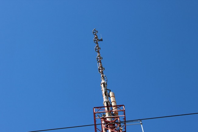
More and more wireless LAN links are being installed between the transmitter and studio. Often these links are used for network extension, remote control, site security, VOIP telephony, and sometimes even as a main STL. These systems come in several flavors:
- Moseley LAN link or similar system. Operates on unlicensed 920 MHz (902-928 MHz) band. Advantages: can use existing 900 MHz STL antennas, can work reliably over longer distances, transmitter, and receiver located indoors. Disadvantages: slow, expensive
- ADTRAN TRACER or similar system with indoor transceivers and coax-fed antenna systems. Operates on unlicensed or licensed WLAN frequencies. Advantages: fast, transmitter and receiver located indoors, can be configured for Ethernet or T-1/E-1 ports. Disadvantages; expensive
- Ubiquiti Nano bridge or similar system where the transceiver is located in the antenna, the system is connected via category 5/6 cable with POE. Operates on unlicensed or licensed WLAN frequencies. Advantages; fast, relatively inexpensive. Disadvantages; equipment located on the tower, difficult to transition base insulator of series fed AM tower.
- Ubiquiti Rocket or similar system where the antenna and transceiver are separate, but the transceiver is often located on the tower behind the antenna and fed with category 5/6 cable with POE. Operates on unlicensed and licensed WLAN frequencies.
For the first two categories of WLAN equipment, standard lightning protection measures are usually adequate:
- Good common point ground techniques
- Ground the coaxial cable shield at the tower base and at the entrance to the building
- Appropriate coaxial-type transmission line surge suppressors
- Ferrite toroids on ethernet and power connections
For the second two types of WLAN equipment, special attention is needed with the ethernet cable that goes between the tower and POE injector or switch. Shielded, UV-resistant cable is a requirement. On an AM tower, the shielded cable must also be run inside a metal conduit. Due to the skin effect, the metal conduit will keep most of the RF away from the ethernet cable. Crossing a base insulator of a series excited tower presents a special problem.
The best way to get across the base insulator of a series excited tower is to use fiber. This precludes the use of POE which means that AC power will be needed up on the tower to power the radio and fiber converter. This may not be a huge problem if the tower is lit and the incandescent lighting system can be upgraded to LEDs. A small NEMA 4 enclosure can house the fiber converter and POE injector to run the WLAN radio. Some shorter AM towers are no longer lit.
Another possible method would be to fabricate an RF choke out of copper tubing. This is the same idea as a tower lighting choke or a sample system that uses tower-mounted loops. I would not recommend this for power levels over 10 KW or on towers that are over 160 electrical degrees tall. Basically, some 3/8 or 1/2-inch copper tubing can be wound into a coil through which a shielded ethernet cable can be run. Twenty to twenty-five turns, 12 inches in diameter will work for the upper part of the band. For the lower part, the coil diameter should be 24 inches.
In all cases where CAT 5 or 6 cable is used on a tower, it must be shielded and the properly shielded connectors must be used. In addition, whatever is injecting power into the cable, ether POE injector or POE switch must be very well grounded. The connector on the shielded Cat5 or 6 cable must be properly applied to ensure the shield is grounded.
In addition to that, some type of surge suppressor at the base of the tower is also needed. Tramstector makes several products to protect low voltage data circuits.
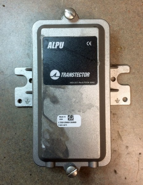
These units are very well made and designed to mount to a tower leg. They come with clamps and ground conductor designed to bolt to a standard copper ground buss bar.
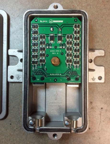
There are various models designed to pass POE or even 90 VDC ring voltage.
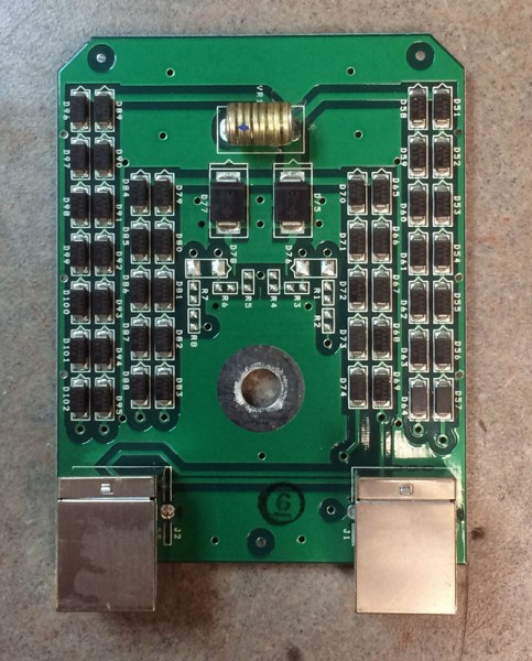
This model is for POE. The circuit seems to consist mostly of TVS diodes clamping the various data conductors.
As more and more of these systems are installed and become a part of critical infrastructure, more thought needs to be given to lightning protection, redundancy and disaster recovery in the event of equipment failure.

