GPS controlled clock based on Raspberry Pi

This is an adjunct to my previous post on creating a Stratum 1 NTP time server with a Raspberry Pi. I finished this project about a year ago, and I have to say it has been running flawlessly since then. I thought that perhaps the inexpensive GPS module designed to work with drones might not hold up. But it has.

Midnight in London

Wouldn’t it be nice to use this time source, not just to set hardware clocks but also display the time in varous places? Yes, yes it would.

Since most of my ideas are not original, I figured a quick internet search may shed some light on how to proceed. Keith, G6NHU did exactly this a year ago or so. His project can be viewed here: https://qso365.co.uk/2023/05/how-to-build-a-shack-clock-using-a-raspberry-pi-and-a-7-touch-display/

As I suspected, with a few more configuration steps, this NTP server can display the time on the native HDMI port as well as create a simple web page available on the LAN for any computer to access with a web browser. The web server is Lighttpd, which is a low CPU load, low memory demon, perfect for an older Raspberry Pi 3.

The display I chose is a 7-inch 16×9 non-touch purchased from Amazon for $33.99: https://www.amazon.com/gp/product/B0BGXB2Y67/ (not an affiliate link)

When I created the NTP server last year, I named it ntpserver. The unit runs headless (no keyboard or monitor) so I use ssh to get into the command line. Thus, the first command is:

ssh ntpserver@192.168.1.200

Once in, always do an update:

sudo apt-get update
sudo apt-get upgrade -y

The following programs need to be added to the Pi:

sudo apt install xorg openbox xserver-xorg xinit unclutter lighttpd -y

If the OS is off the shelf Raspian, then Chromium should already be installed, but if not, then add it:

sudo apt install chromium-browser -y

Once that is done, some things need to be configured. Using whatever text editor you like the xserver so that anyone can access it. Open the Xwrapper file:

sudo nano /etc/X11/Xwrapper.config

Then add line:

allowed_users=anybody

Exit and save. Next open the xserverrc file:

sudo nano /home/ntpserver/.xserverrc

Add the following:

#!/bin/sh
#Start the X server session with no power management so the display never sleeps
exec /usr/bin/X -s 0 -dpms -nolisten tcp "$@"

Exit and save. Next open the xsession file:

sudo nano /home/ntpserver/.xsession

Add the following:

#!/bin/sh
#Start Chromium at startup
chromium-browser --start-fullscreen --window-size=800,480 --disable-infobars --noerrdialogs --incognito --kiosk http://localhost

Exit and save. Note the display size can be configured to any screen resolution. This affects the HDMI port, not the web page. The 7-inch Raspberry Pi monitor that I purchased from Amazon has an 800 x 480 screen resolution. If you are using a different screen resolution, change as needed. Next open the clock.service file (it will be created when you save the file):

sudo nano /etc/systemd/system/clock.service

Add the following:

[Unit]
Description=Clock
After=network-online.target
DefaultDependencies=no

[Service]
User=clock
ExecStart=/usr/bin/startx
Restart=always
RestartSec=10

[Install]
WantedBy=multi-user.target

Exit and save.

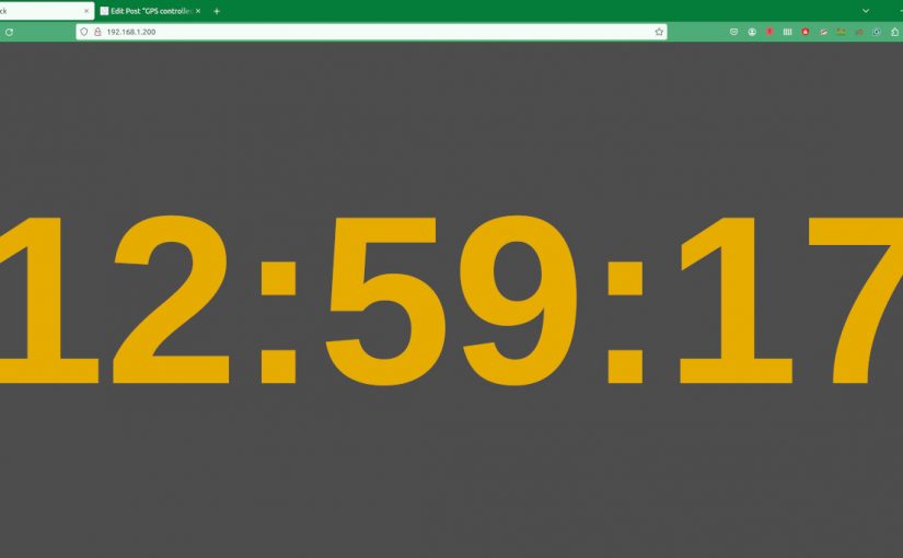
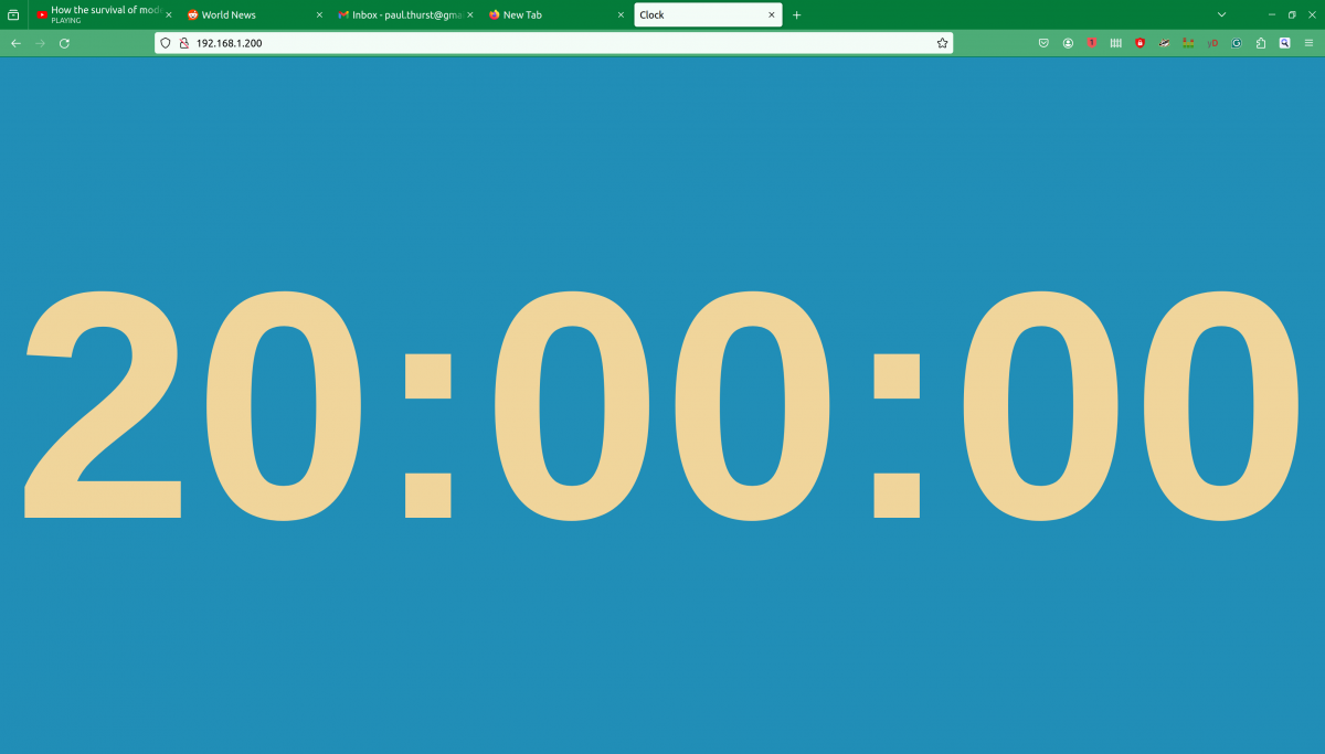
The web page that will be displayed on the HDMI port as well as served to local hosts on the LAN is a java script page. It was originally developed by Nayuki: https://www.nayuki.io/page/full-screen-clock-javascript You can download whatever format you like from that site (I copied the page source) or you can download a 24-hour format from Keith’s site:

cd /var/www/html
sudo wget https://qsl.net/g6nhu/clock/index.html

The colors can be edited:

sudo nano /var/www/html/index.html

The background, foreground, and font type can be changed as desired.

Next start the clock service and reboot:

sudo systemctl enable clock
sudo systemctl start clock
sudo reboot now

Here is a quick video of the web page on my desktop computer. I have the GPS monitor from the ntpserver up and running in the left upper corner. That shows the GPS data going into the Raspberry Pi from the serial port along with some scratchy WWV audio. The actual clock sync is from the 1PPS output of the GPS module.

I could see this being used as an inexpensive master clock system somewhere. With an HDMI splitter (or a better name would be Distribution Amp), this could be sent to many locations.

Now all I need to do is figure out how to get a GPS synced 10 MHz output capable of driving multiple devices.

Special Equipment

This year, winter in the Northeast has been relatively tame (so far). As I type this today, the temperature is 60 degrees F. The average high temperature this time of the year is around 40 F. This is an anomaly due to the strong El Nino currently going on in the Pacific Ocean. Next year will likely be closer to normal.

To that end, one of the problems in winter time is access to mountaintop transmitter sites. Several of the sites we maintain can only be accessed with special equipment such as a snowcat, track machine, or snowmobile. We have two or three sites that are cut off from regular vehicular access for 2-4 months per year. One site in particular has water flowing down the access road from a reservoir creating a 200-foot sheet of ice that is not even walkable.

For many years, I have been on the lookout for some special equipment that will allow us to get there safely and back.

Meet the special equipment:

Polaris Ranger 900 with studded tracks
The wheels were replaced with tracks and we added this stud kit for ice
Polaris Ranger 900

Like other such items, there is a cost associated with owning this. In the past, we have paid a two-way radio company that has a larger snow machine for rides to the top of various mountains. That can get pricey if several trips are needed. We will have to figure out a reasonable fuel surcharge for the operation of this track machine.

Co-located common antenna FM stations

One of our clients needs to move to another transmitter site because their lease is expiring at the old site. We have been working on this for several months now. One of the nice features of this project is the panel antenna.

Kathrein 754154 spec sheet

This is installed in a 2-bay 3-around configuration. I don’t see this particular model in the Kathrein catalog anymore, but there are other cross-polarized panel antennas available from them.

Colocated tower

There are many existing services on this tower including two full-power FM stations, a translator, a VHF TV station, numerous cell carriers, etc. Once the installation is done we will have to check carefully for intermodulation.

Honda Track Machine

Winter in the Northeast; there was just enough snow and slush on the access road that the truck could not make it to the top of the hill. This track machine works great. We have added a Polaris Ranger 900 to our inventory (not this machine) for winter access to several of the more difficult transmitter sites. While I do enjoy the occasional walk in the snow, the key word here is occasional.

AAT branch combiner inputs

The three stations are combined into the panel antenna with this rather nice American Amplifier Technologies C-IR-3-3-30K-N branch combiner.

AAT branch combiner output side

The input filters needed a slight adjustment to compensate for the difference between the test load they were tuned to and the actual antenna load they will be running into

Touching up input filters

Two of the transmitters are Broadcast Electronics STX-10 units. We have had good service from the STX-10 which was installed on Mount Beacon a few years ago.

Pair of BE STX-10 transmitters

We are waiting for the Comrex Bric Link III to come back from the factory after their firmware update. They are to be used for the STL. Once they are returned, we should be good to go for site turn-up.

The Shively 6025 Broadband Log Periodic Antenna

Several companies make variations of this antenna; Scale FM-CL is a lower-power version that is used mostly by translators. They are highly directional and can be installed in a vertical, horizontal, or cross-polarized (45-degree slant) manner. This model input power is 5 KW per bay and the manufacturer’s specification is for 1.28:1 or less VSWR across the entire FM band. In the slant configuration, which Shively states is right-hand circularly polarized, the gain is 4.03 dB.

I recently did some work onsite for WXMD, California, Maryland. They were having some issues with high reflected power readings on their transmitter and suspected an antenna or transmission line problem. The station has been on the air for about 10 years and began having issues late last year after a thunderstorm passed through the area.

WXMD California, MD South East Bay Shively 6025 antenna

The main issue was that the transmitter was showing 243 watts of reflected power with 9800 watts of forward power, while the inline watt meter showed 37 watts. As part of the repairs, a new 1 5/8 transmission line was run up the tower replacing the old line which was damaged at the power divider input connector. A new power divider was also installed. Was the antenna still defective? Was the new transmission line and/or power divider defective? Was there an issue with the inline watt meter? Questions, questions, questions…

Thus, several sweeps were needed to verify things:

1 5/8 inch line terminated at the power divider with known good load

This antenna has a power divider that splits the power between a southeast-facing antenna bay and a southwest-facing antenna bay. To be sure that we were not dealing with a bad connector or transmission line, the line was swept in isolation from the input of the inline watt meter to the input of the power divider. This showed that the transmission line, connectors, elbows, and inline watt meter were all good.

Southeast Antenna SWR
Southeast antenna return loss

Next, each antenna bay was swept individually. The power divider port going to the disconnected antenna was terminated with a known good 50-ohm load.

Southwest antenna SWR
Southwest antenna return loss

Once the individual bays, jumpers, and power divider tested good, the entire antenna system was swept.

Full antenna SWR

With everything connected, the SWR showed 1.19:1. Not ideal but not terrible either. The inline watt meter readings were verified with a precision watt meter and the final SWR calculated by hand was 1.16:1.

Full antenna return loss

Therefore, the antenna system is performing within the manufacturer’s specifications.

Network analyzer

The American Amplifier Technology inline FM watt meter was then checked with a precision power meter. The readings on that device were more or less in line with the precision power meter, thus the transmitter directional coupler is out of calibration.

Mini-Circuits Precision Power meter, Forward Power
Mini-Circuits Precision Power meter, Reflected Power

The transmitter shelter is just large enough for one rack. Thankfully, the weather was cooperative, we were able to work outside. Overall, it was a productive trip and an enjoyable experience.