I pulled this out of the published posts and updated it.
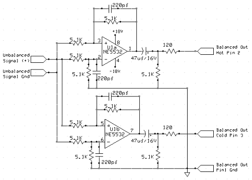
I have been working on updating some wiring at one of our client’s transmitter sites. I noticed that an off air monitor feed was going back to the studio on a Barix box, which is fine. It was being fed from a balanced output of a DA to the unbalanced input on the Barix box. This being at the transmitter site, was susceptible to RF noise. I decided to make a passive audio BALUN.
In any case, there are several ways to go from balanced to unbalanced without too much difficulty. The first way is to wire the shield and Lo together on the unbalanced connector. This works well with older, transformer input/output gear, so long as the unbalanced cables are kept relatively short.
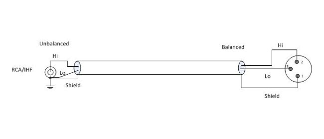
Most modern professional audio equipment has active balanced input/output interfaces, in which case the above circuit will unbalance the audio and decrease the CMRR (Common Mode Rejection Ratio), increasing the chance of noise, buzz, and so on getting into the audio. In this case, the CMRR is about 30 dB at 60 Hz. Also, newer equipment with active balanced input/output, particularly some brands of sound cards will not like to have the Lo side grounded. In a few instances, this can actually damage the equipment.
A Henry Match Box or something similar can be used. I have found, however, the active components in such devices can sometimes fail, creating hum, distortion, buzz, or no audio at all. Well-designed and manufactured passive components (transformers and resistors) will provide excellent performance with little chance of failure. There are several methods of using transformers to go from balanced to unbalanced or vice versa.
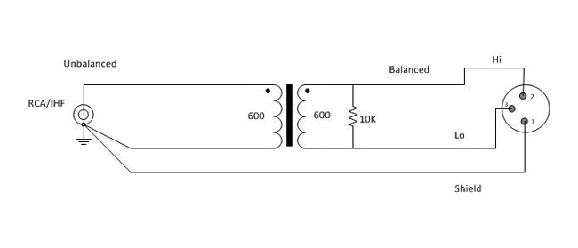
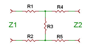
Using a 600:600 ohm transformer is the most common. Unbalanced audio impedance of consumer-grade electronics can vary anywhere from 270 to 470 ohms or more. The 10,000-ohm resistor provides constant loading regardless of what the unbalanced impedance. In this configuration, CMMR (Common-Mode Rejection Ratio) will be 55 dB at 60 Hz, but gradually decreases to about 30 dB for frequencies above 1 KHz.
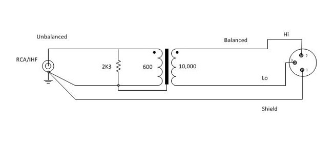
A 600:10,000 ohm transformer will give better performance, as the CMMR will be 120 dB at 60 Hz and 80 dB at 3 KHz, remaining high across the entire audio bandwidth. The line balancing will be far better for the high-impedance load. This circuit will have about 12dB attenuation, so plan accordingly.
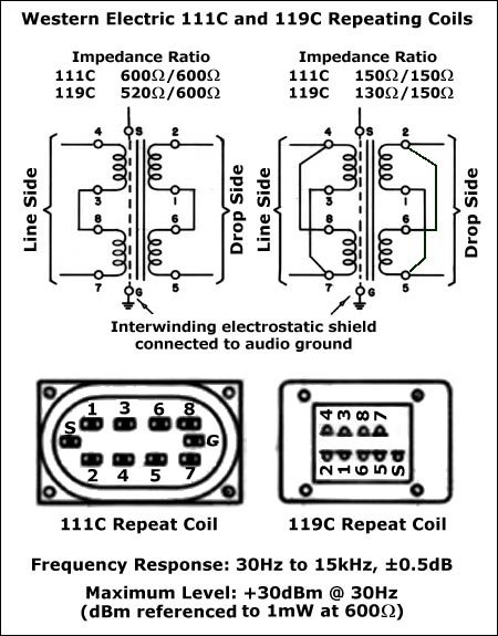
For best results, use high-quality transformers like Jensen, UTC, or even WE 111C (although they are huge) can be used. I have found several places where these transformers can be scrounged, DATS cards on the old 7300 series Scientific Atlanta satellite receivers, old modules from PRE consoles, etc. A simple audio BALUN can be constructed for little cost or effort and sound a whole lot better than doing it the wrong way.
A brief list, there are other types/manufacturers that will work also:
| Ratio | Jensen | Hammond | UTC | Edcor |
| 1:1 (600:600) | JT11E series | 804, 560G | A20, A21, A43 | PC600/600 |
| 4:1 (10K:600) | JT10K series | 560N | A35 | PC10K/600 |
Keep all unbalanced cable runs as short as possible. In stereo circuits, phasing is critically important, so pay attention to how the balanced transformer windings are connected.
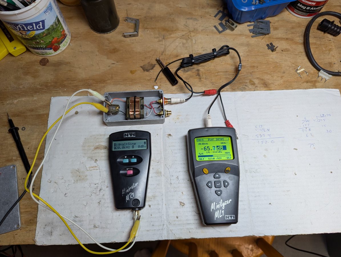
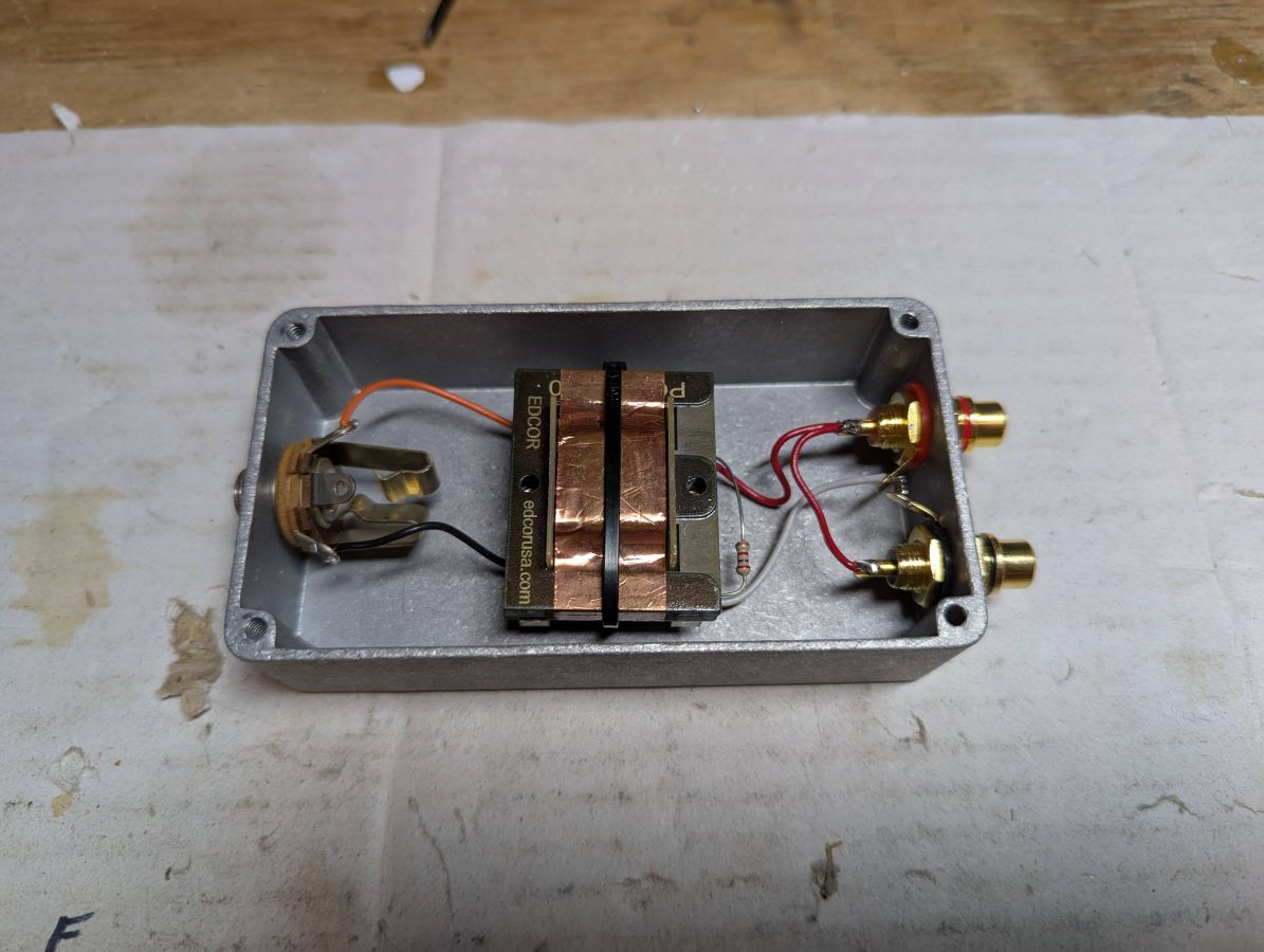
As for cost; I purchased the Edcor PC10K/600 transformer on eBay for $20.00 and the Hammond 1590B Enclosure was about $9.00. The audio jacks and resistor were in the parts drawer. It took about 20 minutes to layout the holes, drill, mount the audio jacks, and solder the jumper wires. I used a tie-base, wire tie, and some Gorilla glue to hold the transformer down. I used a 1/4 inch TRS jack because the enclosure was a little bit too small for an XLR jack. If a stereo pair needed be converted, it would require two of everything.
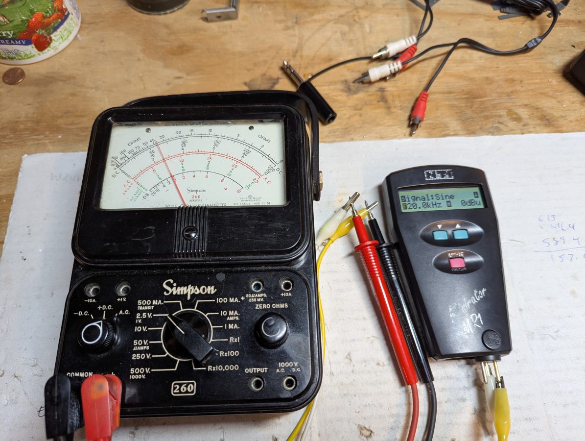
Overall, I fun project. The old Simpson 260 is still accurate!
