There are four of these stations in Canada. In my scanning of the shortwave frequencies, I have found CFRX on 6070 KHz to put a strong signal into my location pretty much 24/7. At night it is drowned out by interference but daytime is listenable from local sunrise until about an hour before local sunset with a 100 uv signal. A look at the map reveals the CFRX transmitter site is roughly 300 miles away. CFRX is a relay of CFRB, 1010 KHz in Toronto, Ontario, Canada. CFRB does not come in here at all due to protecting 1010 WINS in NYC.
1964 CFRX/CFRB QSL card
What I find very interesting is the station uses 1 KW TPO into a single 50-foot (117-degree) vertical tower. That is a pretty low-tech transmission facility, nothing like the minimum 50 KW with a 10 dB antenna requirement the FCC stipulates for shortwave broadcasters in this country. Even so, it generates a big useable signal, in the case of CFRX, covering nearly 300,000 square miles very inexpensively.
CFRX has been relaying CFRB’s signal since 1937. According to the ODXA site, the station uses a Bauer 701B modified to transmit on HF. The Bauer transmitters were always solid units. It went off the air in 2008 for several months while the transmitter was repaired, but eventually, it did return. Obviously, the station ownership finds value in the service and it continues today.
I often wonder why the FCC won’t allow a similar HF relay service here in the US. Daytime propagation on the tropical bands (75 and 60 Meters (3.9-4 MHz and 4.7 – 5.06 MHz respectively)) would allow low-power relays to cover large areas like CFRX. Tropical band propagation is such that nighttime coverage may be degraded by interference from other, more powerful stations offshore. Even so, it seems like a good way to cover a lot of ground in an economical way.
Other Canadian shortwave relay stations:
HF Call sign
Power/frequency
Parent station
Location
Power/frequency
CFRX
1000/6060
CFRB
Toronto, ON
50 KW/1010
CFVP
1000/6030
CKMX
Calgary, AB
50 KW/1060
CKZN
300/6160
CFGB (CBC R-1)
St. Johns, NF
4.5 KW/89.5 MHz
CKZU
500/6160
CBU (CBC R-1)
Vancouver, BC
50 KW/690
Power in watts, frequency is KHz unless otherwise noted.
I know the CRTC would like to do away with these stations, but I think that is foolish.
For those of you who are interested in radio listening, particularly over long distances (AKA DXing) with even a moderately directional antenna, having a great circle map projection for your location is a necessity. Looking at a Mercator Projection, the normal “flat” map most are familiar with, one might come to the conclusion that due west from upstate NY lies the Washington/Oregon state border. Appearances can be deceptive, bearing away at 270 degrees true (due west) from upstate NY is the California/Mexico border.
This is because we live in a big sphere. In this regard, the only place the Mercator Projection is accurate is around the equator unless one is going due north (0 degrees) or due south (180 degrees). The further north or south from the equator, the less accurate a flat map is. Therefore, having a Great Circle map projection based on your location is handy for choosing the right azimuth to listen along.
As with many things, the internet provides the required tools to generate a great circle map for any location in the world. The first thing needed is an accurate fix of your location. This can be obtained via GPS, or, if you know how to look at a map and or satellite picture, itouchmap can be very useful. Once you know where you are, you can plug that information into this Great Circle Map Generator.
I saved the image as a bit map and used it as the wallpaper on my computer. That way, I just need to minimize any running programs and I can see what the correct azimuth is to any place in the world. This is for upstate NY:
A quick glance at almost any circuit board these days will show that almost all of the components are surface-mounted. They are small rectangles or squares that sit on top of the circuit board. This is different from the through-hole components that were used for many years and are still found in older equipment. There are radio engineers who feel that surface mount components are too hard to work on, thus the boards are not repairable.
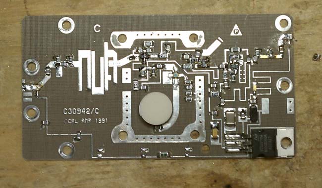
California Amplifiers C band block down converter
As with anything in the engineering field, there needs to be a cost/benefit analysis. Most computer component boards, things like NICs, modems, sound cards, VGA cards are very inexpensive, and often times it would be more expensive to repair the board than it would to buy a new one. In other situations, however, local repair of circuit boards makes good sense and can be a good learning tool.
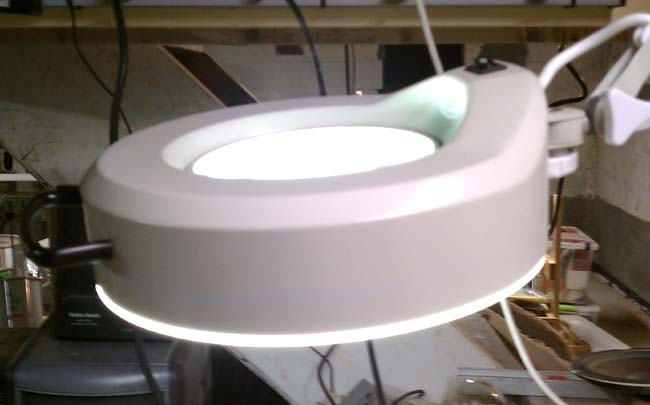
Consoles and transmitters offer some good opportunities for local repair, provided the schematics are available. SMT component troubleshooting is the same as through-hole troubleshoots, except the components are smaller. That is where a magnifying glass comes in handy. I purchased a magnifying glass/light to work on SMT boards.
three diopter magnifying lamp
Soldering and unsoldering techniques are also different. A temperature controlled soldering iron with a small tip is important. I find the easiest way to unsolder a component is with solder wick. Once most of the solder has been wicked up, a brief touch of the iron and the component will come off. Small resistors and capacitors are fairly rugged, but should not be overheated. Semiconductor components such as diodes, transistors and ICs are susceptible to heat damage and Electro Static Discharge (EDS). A grounding wrist strap should always be used when handling semiconductor components. Soldering iron temperature should be enough to quickly melt the solder and heat the connection surface without overheating the SMT component. Lead free solder requires slightly higher temperatures than the traditional 60/40 rosin core.
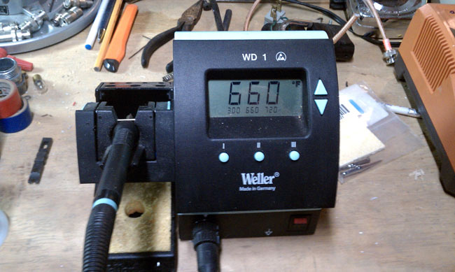
Weller WD1 temperature-controlled soldering station
A temperature-controlled soldering station is a must. Too much heat will damage components and boards, too little will make soldering SMT an arduous task.
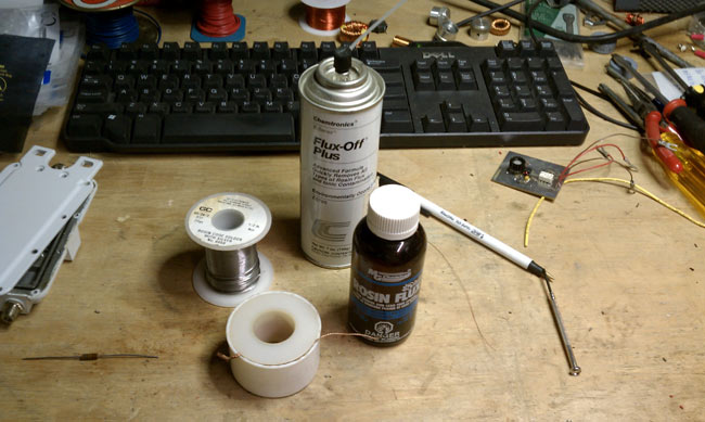
Soldering supplies
Other soldering supplies include liquid flux, desoldering wick, flux remover and 55/40/5 solder. The desoldering wick makes it easy to clean up an errant solder deposits and is the best way to desolder surface mount components. I have had limited success using a solder pump on surface mount boards. They do come in handy for RF MOSFETS, which have large tabs, often with liberal amounts of solder applied at the factory.
Soldering new components:
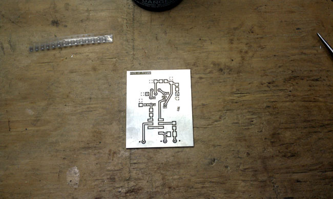
HF receiver preamp SMT board
A typical 0.1 uf capacitor is placed on the surface mount board and ready to be soldered. These components are all small, but I would characterize this as a medium sized one. There are some very small diodes, ICs and other devices that require the magnifying glass to identify pins and polarity.
The best way that I have found to solder components onto a surface mount board is to use a little bit of liquid flux on the board.
Using tweezers or small needle nose pliers, place the component.
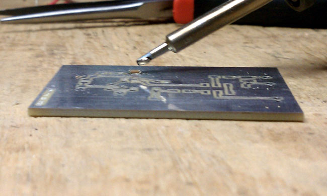
Soldering 0.1 uf bypass cap on SMT board
Wet the end of the soldering iron with a little bit of solder.
Using the placing tool, hold the component in place and touch one of the pads with the soldering iron. This should tack the component in place. Solder the component to the other pad using the soldering iron and solder. Then come back and touch up the tacked side. I have found that 600 degrees F is a good temperature to quickly melt the solder, while not heating up the component too much.
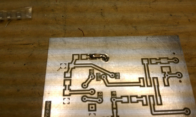
HF receiver preamp with bypass capacitor soldered
Sorry I could not get pictures of the actually process, I don’t have enough hands to hold the soldering iron, hold the component down and take a picture.
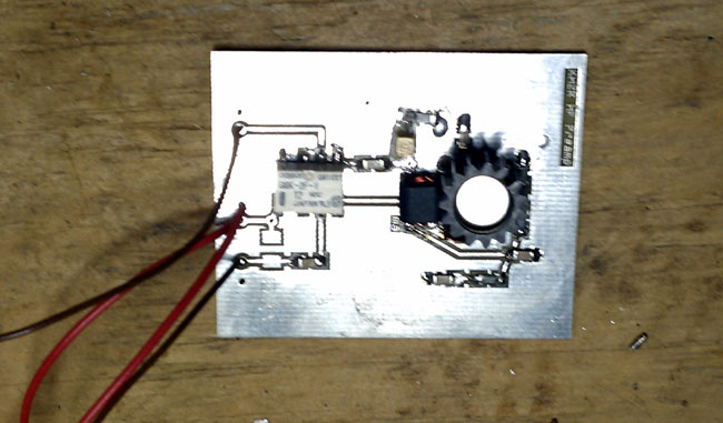
HF preamp based on Norton 1N5109 design
The completed preamplifier. I have been calling this an HF preamp, because that is its intended use. In practice, this preamp should work well from 50 KHz up to about 75 MHz, with 3dB points at 30 KHz and 100 MHz.
Norton HF preamp Schematic
The Norton design is an inverse feed back and using the 1N5109 transistor, which has input and output impedance of 50 ohms, makes it simple to implement. In testing, I found this unit has about 10-11 dB of gain with about 4 dB of noise. The use of SMT makes the design stable and I didn’t see any evidence of oscillations when testing it. More on the preamp here. I installed it out at the base of my K9AY antenna and it can be remotely turned on and off as needed. My main reason for wanting it is to overcome the 6.5 dB signal loss in the four port hybrid receiver coupler and transmission line I use. Truth be told, most of the time it is off.
Sounds like some dire prediction, but no, actually it is a good radio show heard on Shortwave, WWCR-2 to be precise. The show, at least during the weeks that I heard it, consisted of blues and other music that you likely won’t hear anywhere else. Allan Gray, the host, also often interviews musicians and other persons of note. I stumbled on this show a few weeks ago while listening to 12,160 KHz on Saturday afternoon. WWCR is touted as “World Wide Christian Radio” and there are many religious shows to be sure. They also air several secular programs like World of Radio, Golden Age of Radio, DX Partyline and Ask WWCR and Info Wars, and others.
Allan Gray
From reading their schedule, Last Radio Playing can be heard on WWCR-2 Tuesdays at 5 pm est (5,070 KHz), Saturdays and Sundays at 3 pm EST (12,160 KHz), and on WWCR-3 at 8 pm (4,840 KHz). WWRC is located in Nashville, TN. They have four Continental 418 HF transmitters with a carrier power of 100 KW each. WWCR-2 uses an azimuth of 85 degrees true and WWCR-3 uses an azimuth of 40 degrees true, both into Rhombic antennas with 14 dBi gain.
Today the show consisted of Christmas Music, which on the AM wide band receiver, sounded pretty good. Anyway, if you are so inclined, tune in and take a listen.