The Realtek 2832U

In my spare time (lol!) I have been fooling around with one of those RTL 2832U dongles and a bit of software.  For those that don’t know, the RTL 2832U is a COFDM demodulator chip designed to work with a USB dongle.  When coupled with an R 820T tuner a broadband RF receiver is created  There are many very inexpensive versions of these devices available on Amazon, eBay, and other such places. The beauty of these things is that for around $12-30 and a bit of free software, one can have a very versatile 10 KHz to 1.7 GHz receiver.  There are several good software packages for Windoze, Linux, and OSX.

The one I recommend for beginners is called SDR-Sharp or SDR#.  It has a very easy learning curve and there is a lot of documentation available online.  There are also several worthwhile plugins for scanning, trunking, decoding, etc.  At a minimum, the SDR software should have a spectrum analyzer, waterfall display, and the ability to record audio and baseband PCM from the IF stage of the radio.

Some fun things to do; look at the output of my reverse registering smart (electric) meter (or my neighbor’s meter), ACARS data for the various aircraft flying overhead, a few trips through the EZPass toll lanes, some poking around on the VHF hi-band, etc.  I also began to think of Broadcast Engineering applications and a surprising number of things came to mind:

  • Using the scanner to look for open 950 MHz STL frequencies
  • Inexpensive portable FM receiver with RDS output for radio stations
  • Inexpensive Radio Direction Finder with a directional antenna
  • Inexpensive Satellite Aiming tool

Using SDR sharp and a NooElec NESDR Mini+ dongle, I made several scans of the 945-952 STL band in a few of our markets.  Using the scanner and frequency search plugin, the SDR software very quickly identified all of the in-use frequencies.  One can also look at the frequency span in the spectrum analyzer, but this takes a lot of processing power.  The scanner plugin makes this easier and can be automated.

950 MHz STL frequencies, Albany, NY
Analog and digital 950 MHz STL frequencies, Albany, NY

I also listened to the analog STLs in FM Wideband mode.  Several stations are injecting their RDS data at the studio.  There is one that appears to be -1500 Hz off frequency.  I’ll let them know.

Next, I have found it beneficial just to keep the dongle and a small antenna in my laptop bag.  Setting up a new RDS subcarrier; with the dongle and SDR# one can quickly and easily check for errors.  Tracking down one of those nasty pirates; a laptop with a directional antenna will make quick work.

Something that I found interesting is the waterfall display for the PPM-encoded stations:

WPDH using RTL 2832U and SDR Sharp

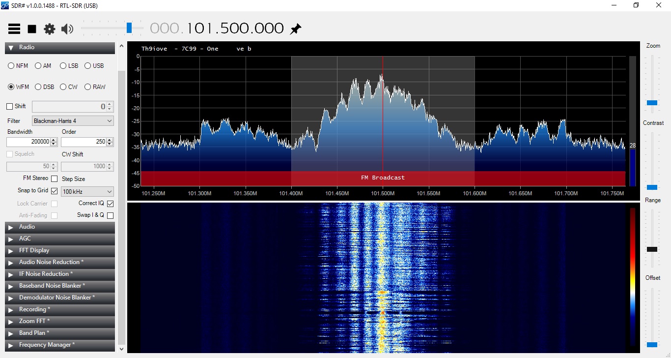
Not only can you see the watermarking on the main channel, you can also see the HD Radio carriers +/- 200 KHz from the carrier frequency.  That is pretty much twice the bandwidth allotment for an FM station.

WDPA using RTL 2831U with SDR Sharp
WDPA using RTL 2831U and  SDR Sharp

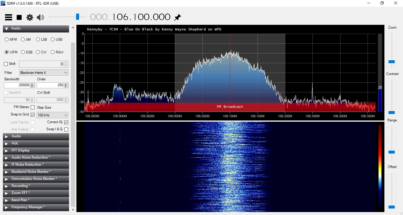
Those two stations are simulcasting.  WPDA is not using Nielson PPM nor HD Radio technology.  There is all sorts of interesting information that can be gleaned from one of these units.

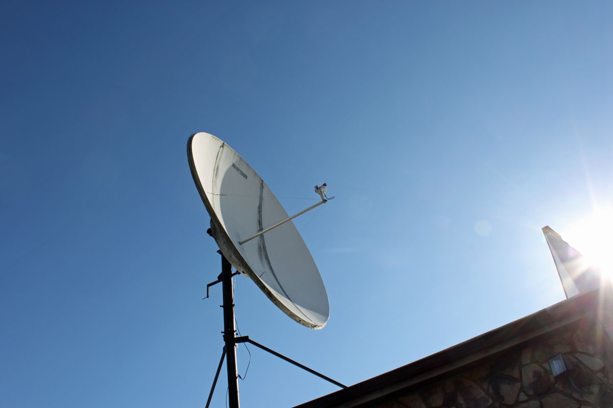
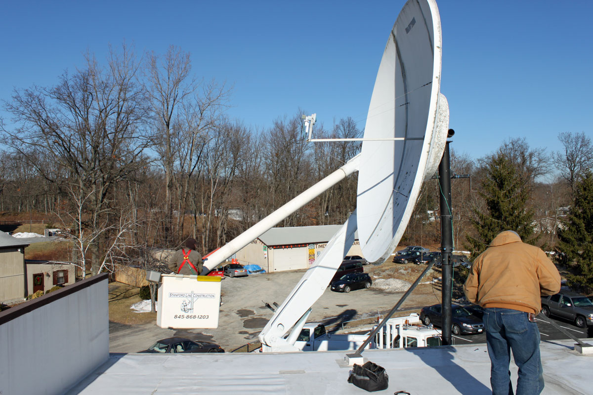
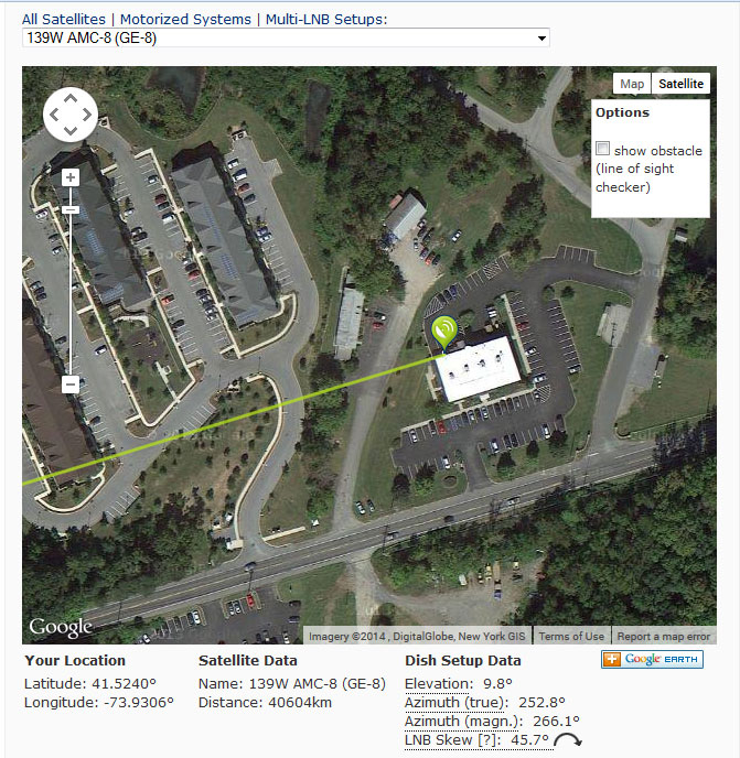
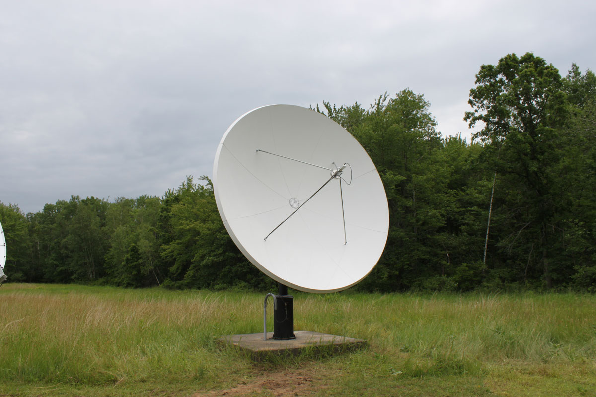
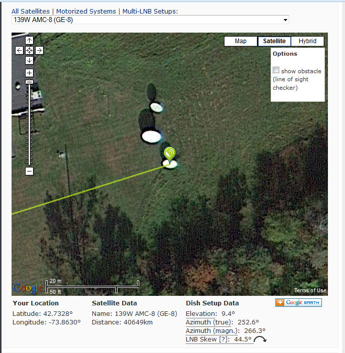
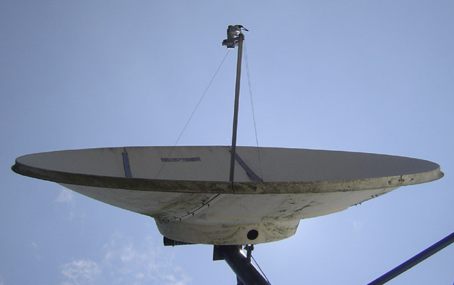
Aiming a satellite dish at AMC-8 can be a bit challenging.  That part of the sky is pretty crowded, as it turns out.  Dish pointer is a good general reference (www.dishpointer.com) and the Dish Align app for iOS works well.  But for peaking a dish, the RTL 2832 dongle makes it easy to find the correct satellite and optimize the transponder polarization.  Each satellite has Horizontal and Vertical beacons.  These vary slightly in frequency, thus, but by tuning to the correct beacon frequency, you can be assured that you are on the right satellite.  All of the radio network programming on AMC-8 is on vertically polarized transponders, therefore,  the vertical beacons are of interest.  Here are the vertical beacons for satellites in that part of the sky:

Satellite Position C band Vertical beacon (MHz) L band (LNB) Vertical beacon (MHz) Comment
AMC-8 139W 4199.5 949.25
AMC-7 137W 3700.5 1450.25
GOES15 135.4W 2209.086 N/A NOAA WX
AMC-10 135W 4199.5 949.25
Galaxy 15 133W 4198 949.00
AMC-11 131W 4199.5 949.25
Galaxy 12 129W 3700.5 1450.25

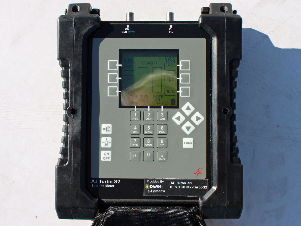
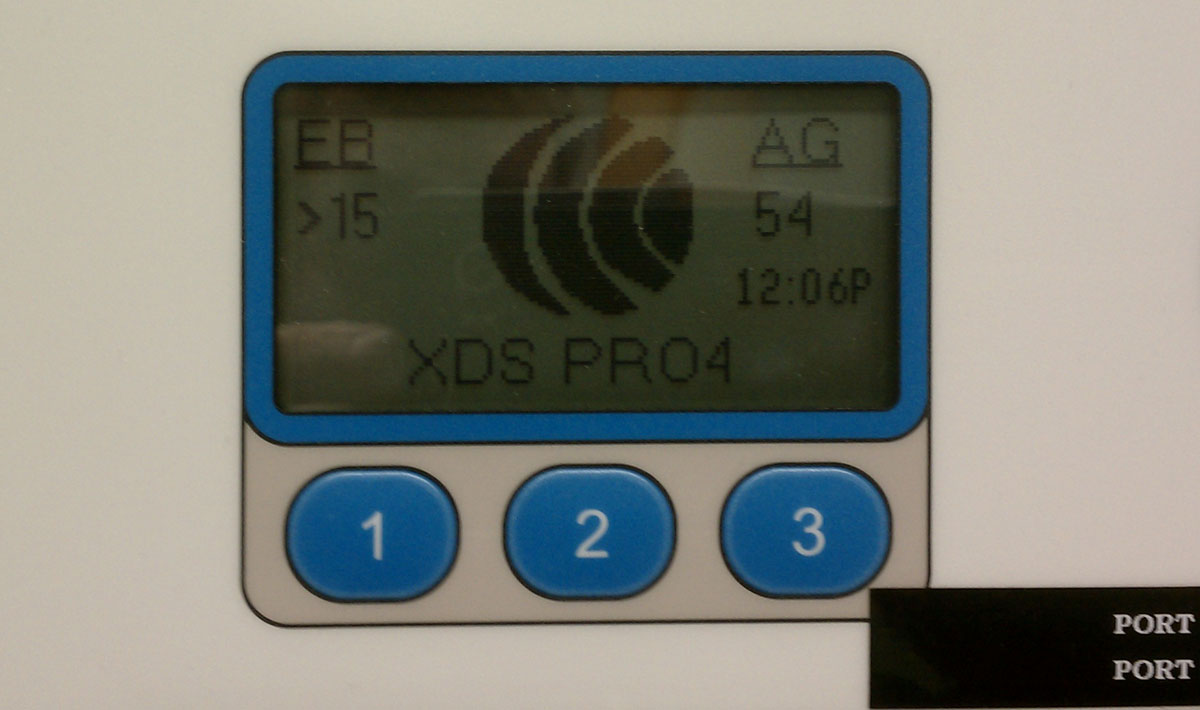
For those in the continental United States, there is not much else past 139W, so AMC-8 will be the westernmost satellite your dish can see.  Of course, this can be used in other parts of the world as well, with the correct information. Bringing a laptop or Windows tablet to the satellite dish might be easier than trying to drag a XDS satellite receiver out.

AMC8 vertical beacon output from LNB

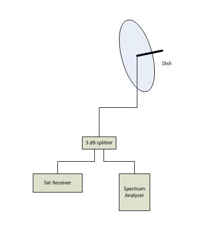
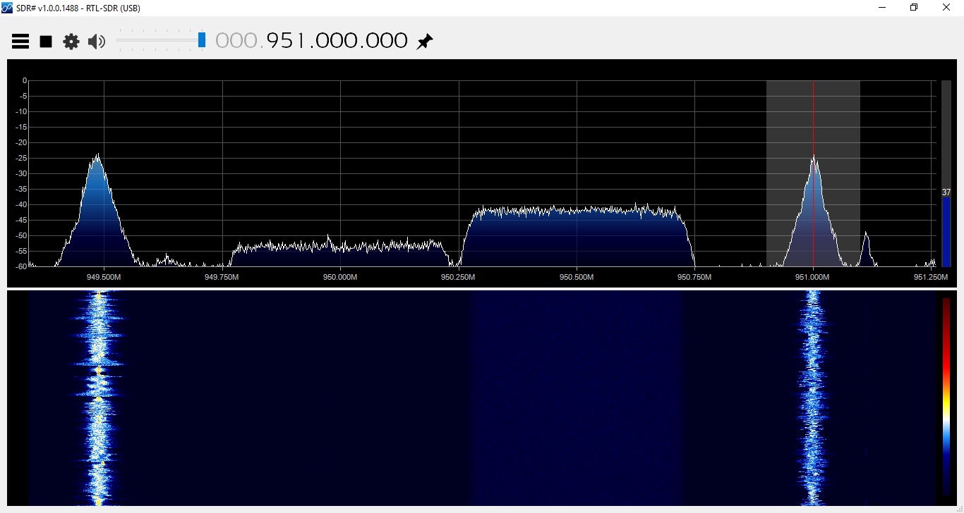
In order to use the RTL-2832U, simply split the output of a powered LNB, and install a 20-30 dB pad in between the splitter and the dongle.  Using the vertical beacon on 949.25 MHz, adjust for maximum signal.

For some other uses; look for the nearest and best NOAA Weather radio station.  Several times the local NOAA weather station has been off the air for an extended period of time.  Sometimes, another station can be found in the same forecast area.  Heck, couple these things to a Raspberry Pi or Beaglebone black, and a really nifty EAS receiver is created for NOAA and broadcast FM.  One that perhaps, can issue an alarm if the RSL drops below a certain threshold.

I am sure there are plenty of other uses that I am not thinking of right now…

Satellite Dish Maintenance

Periodic attention is required for most satellite receive-only earth stations. This particular dish sticks up above the roof line of a two-story building. It acts as a big sail and sometimes, after a particular wind event, it gets slightly off of its intended satellite, AMC-8.

Comtech 3.7 meter dish

The real issue is doing nothing with the feed horn assembly, as it hangs way up in the air right over the edge of the roof. An extension ladder does not work, nor does a step ladder on the roof. Thus, we had to call a bucket truck to come and replace the LNB.  Naturally, this work is being done on one of the coldest days of the year (so far).  Temperatures at the start were 4° F or -15° C, which made the hydraulics in the bucket truck a bit reluctant to work.

When the dish was installed in 2000 or so, I swung it so the feed horn assembly was over the roof to work on it. This did not allow me to effectively check the feed horn polarization. With the bucket truck and a good satellite aiming device, I was able to find the correct polarization for the transponders in use by this station.

Bucket truck satellite dish maintenance

The old LNB was an original California Amplifiers PLL LNB from the mid 1990’s. The temperature was 35° K, which is kind of high these days. It was replaced by a Norsat C band PLL LNB with a 20° K temperature.

The satellite aiming tool used is an AI Turbo S2 by Dawn Satellite.  This unit has software profiles for each satellite which can be updated over the internet.  The 139° W satellite neighborhood is pretty crowded and it is easy to find yourself looking at the wrong bird.  Using the aiming tool prevents that from happening, as it tells the user exactly which satellite it is receiving.

Satellite aiming tool

If this is a new installation, using Satellite Finder makes the rough aiming much easier.

Dish pointer, AMC-8 aiming information

Also, it one were interested in being very thorough, consulting the SES center of box page will give the best aiming window times.  To be honest, I have never found this to make much difference.

XDS Eb/No after re-aiming

The end result, Eb/No is 17.5 with an AG of 54.  All in all, a happy satellite receiver.

Mounting a new satellite dish

Something that almost every radio station has but no one really thinks about; is the satellite downlink. I think radio stations began installing satellite downlink equipment around 1982. Before that, all network programming was carried hither and yon via Ma Bell’s extensive terrestrial microwave network.

Those early dishes were almost always Scientific Atlanta 9000 series 2.8-meter antenna system, which went with the SA 7300 DATS satellite receiver.  Fast forward 31 years and things have changed.  The satellite constellation is now spaced at one degree and those old SA 9000 dishes are not one-degree compliant.

Scientific Atlanta 9000 series satellite dish

Therefore, when it came time to re-aim a dish at AMC8, something new was required.  A Prodelin 1374 3.7 meter center-fed C band dish was ordered up.

The first thing to do is look at the dish specifications and decide if the suggested mounting procedure is a good one.  The soil in this area is sandy loam.  The mounting design calls for a six-inch schedule 80 steel pipe at least six feet into the ground.  This calls for renting an excavator, digging a six-foot deep hole, buying a 36-inch sono-tube and a 16-foot piece of 6-inch schedule 80 steel pipe, and a couple of yards of concrete from a truck.  This work is all being done on the ground system for the WDCD antenna array.  All the while, abandoning the old pad and dish in place.  Seems like a lot of money and wasted materials.  Reusing the old pad and part of the old mount made more sense.  I did some rough calculations on paper regarding wind forces, this was the results:

WDCD satellite dish mount design

The maximum static force is 1,555 N on the back bolts of the mounting ring into the concrete pad.  Maximum wind force is 5,603 N, and a maximum wind from bearing 76° T will exert a force of 7,158 N or 730 Kg force on the back bolts of the mount.  The concrete that the mounting bolts is embedded in will withstand 4,267 Kg of force at six inches deep.  The the existing pad and 3/4 inch J bolts are well within their rating to handle this load, so it seems like a good design. Putting that to practical use:

Scientific Atlanta 9000 series dish mount

First, we unbolted the azimuth mounting ring and removed the old dish, leaving the bottom of the mount.  I drilled down 6 inches into the old concrete pad and inserted 1/2 inch re-bar.  These re-bar are somewhat diagonal toward the center of the tube towards the new mounting pole.

Scientific Atlanta 9000 series dish mount reuse

Then, we placed the 6 inch by 8 foot schedule 80 pipe in the center of the tube and attached it to the tube with 1/2 inch all-thread.  We used the all thread to adjust the 6-inch pipe to be vertical.

Next, we filled the old mount up with 4,000 PSI (280 Kg/square cm) ready-mix concrete and let it cure for one week.

New mount for Prodelin dish

While that was curing, I bolted the new Prodelin 1374 dish together on the ground.  Follow the directions closely on this one, there are many pieces of hardware that look the same and are almost the same but will not work if exchanged.

Prodelin 1374 dish about to be lifted

We used a loader with a lifting bar on it to sling the new dish into place.  I was going to video tape this evolution, but we were short handed and I ended up helping bolt the dish on the mount once it was placed there.

Prodelin 1374 dish, installed

Once the dish was mounted, I installed the feed horn and LNB.

WDCD Albany, NY, Prodelin 1374 dish installded
WDCD Albany, NY, Prodelin 1374 dish installed

Then there was the aiming; this dish is pointed at AMC-8, for which I found this information from dishpointer.com most helpful:

WDCD AMC-8 information, courtesy of dishpointer.com

This is a crowded neighborhood and finding the right satellite took a bit of trial and error.

Center of Box, AMC-8

Satellite dishes have been a part of radio station technical equipment for years. I am surprised at the number of broadcast engineers that do not consider center of box when aiming dishes. As dishes get larger and focal points get smaller, center of box aiming is not a nice thing to do, it is a necessary thing to do.  The latest generation of satellite receivers, (AKA XDS) have a somewhat less than lively RF front end, they require higher E/B than the previous generation Starguide receivers to stay locked.

For years, the majority of commercial radio networks were carried on AMC-8 or its predecessors living at 139° W.  On the East Coast, particularly in the Northeast, that makes aiming points relatively low to the horizon, anywhere between 8-10° elevation.

3.2 meter comtech dish
3.2 meter COMTECH satellite dish

This all means that precise aiming the satellite receive dish is critical for satisfactory performance. SES Americom owns AMC-8 and thus they have a web page about all of their satellites and important operating information. SES Center of box for AMC-8 is available in one-month blocks, which makes scheduling the aiming chore fairly easy.

Large satellite dish aiming diagram

I have always used a spectrum analyzer through a 3 dB splitter to look at the 950 MHz  LNB output.  This aiming setup allows the best combination of Azimuth/Elevation/polarization.  Using the satellite receiver to confirm and maintain signal lock, peak the waveform that the  receiver is locked to.  It is pretty crowded up there, so there will be lots of signals on the spectrum analyzer trace.

It is a pain in the rear end to lug all that equipment out to the satellite dish, especially if it is on the roof.  That is why it only need be done once; the right way the first time.

Any shortcuts will likely lead to those annoying chirps and dropouts or complete loss programming, particularly when the weather turns bad.