Bell System microwave relay system

This is a map of the AT&T microwave relay system as it was in 1960. It is interesting for several reasons.  First of all, before there were communications satellites, this is the way that data was transferred from one location to another.  That data would have been digitized and TDM encoded on a T-carrier, then loaded onto a microwave path.  TV networks had loops that transversed the country, distributing network video and audio to all the markets in the US.  The first transcontinental New York to San Francisco microwave route was established in 1951.  Through the fifties and sixties, the network was filled in across the US and Canada.

Radio networks had been using wired TELCO networks for program distribution for years, although they required far less bandwidth than TV.  This was during the time when network affiliation was vitally important to a station.  Radio networks provided news and other special event programming, as well as some long-form shows which were an important source of information for the listeners.  Any network programming prior to 1980 or so would have been carried by this system.

It was not until the use of C and Ku band satellite services that networks could offer multiple channels of programming.  Now, entire radio formats could be programmed remotely and beamed into hundreds of stations across the country simultaneously.  That would have been far too expensive to implement over TELCO lines, as the line charges were based on the mileage of the circuit.
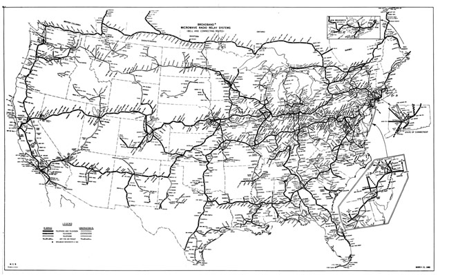
Bell System microwave relay routes

Click for higher resolution.

This system included thousands of hardened microwave relay sites, each built to exact specifications and fully redundant.  At the time, the long-distance telephone system was an integral part of the US defense planning.  Sites were spaced 20-40 miles apart, depending on terrain.  In congested areas, like the northeast, area mountain tops are dotted with these sites today, mostly empty.  Most of these sites went offline in the late 1990s as phone companies switched to fiber optic cables for telephone and data traffic.

American Tower, Inc. purchased most of these sites in bulk from AT&T in the year 2000.  Some sites are well positioned for Cellular Telephone, 3G, and 4G wireless data services, plus other things like Media Flow and general use applications like FM broadcast and two-way.  Many sites, however, do not meet any specific needs and sit empty.  There was a large fire sale by American Tower in 2002 in which they unloaded about 1,900 of these sites as they were redundant.

I wrote a post titled Cold War Relic: ATT long lines site, Kingston,NY detailing one of these sites near me.  Keep in mind, there were thousands of these sites throughout the country.

TIA/EIA 568

Radio stations more and more revolve around networked computers.  Engineers need to understand computer networking, especially as it relates to audio distribution and playback.  Eventually, I see broadcast engineers being more computer science types rather than electrical engineering majors.

What I have found out about computer networking is this: it is not rocket science.  In fact, most of it is pretty easy.  Physical networking and cabling are similar to audio and TELOC cabling.  Automation computer servers themselves are not difficult to understand as most of them run on some type of Windows program.  Other servers such as Apache for WWW and for FTP and streaming run on some type of LINUX OS.  LINUX is also not difficult to understand so long as one knows the right command line prompts.

The first part of understanding computers is networking.  Without a computer network, a computer is a glorified typewriter.  Almost every automation system and or digital editor requires some type of network.  Consoles and computers that use AOIP require well-constructed networks in order to operate properly.  To that end; cabling choices, network interface devices such as switches and routers, patch panels, and so forth need to be specified and installed with care.

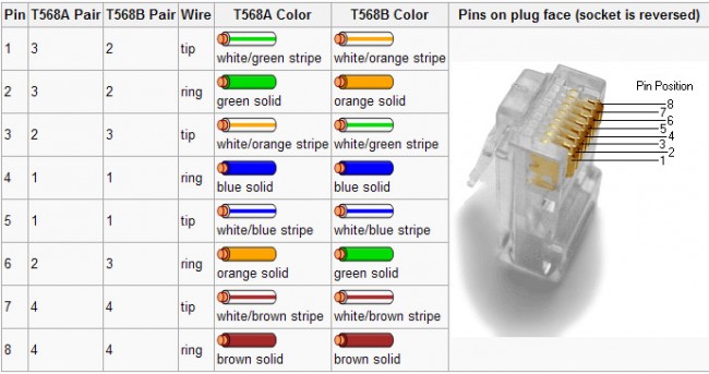
Most often, it is the simple things that will trip an installer up.  The one area where I have found the most mistakes made is the pair’s connection to various termination points.  There are two basic standards, TIA/EIA T568A and T568B.  Neither is better than the other, both are often identified on terminating devices such as jacks and patch panels.  The most important aspect of these standards for an installer is to pick one and stick with it.

TIA/EIA 568 color code

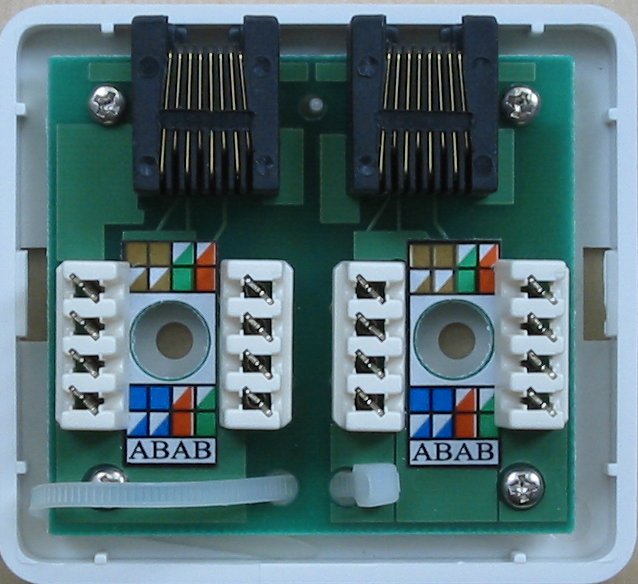
When certifying networks, the most common problem I have encountered is crossed pairs.  Almost invariably, one end will be punched down with the A standard and the other with the B standard.  Jacks are particularly difficult, as the color-coding stickers show both.  Many patch panels have a slide-out, reversible card with is an either/or situation.  For some reason, I have stuck with the B standard, and on any project I am managing, I get rid of all the A color codes I can find and tell the installers that B is the only acceptable termination standard.  That cuts down on a lot of errors and redos during certification.  That is good, it saves time and I hate redos.

Cat 5e wall jack set

You can see that this color code marking can lead to confusion.  I take a sharpie and cross out all the A markings to avoid installation mistakes.

Incidentally, on any new network installation, Category 6 cable should be used.  As more and more data throughput is required for network applications,  Category 6 Cabling has better performance specs and will likely have a longer service life than another cable.   It may be a little bit more expensive than Cat 5,  however, well worth the investment.  It would be a great mistake and a waste of money to have to pull out the network and reinstall it in a few years because the cabling doesn’t have the required bandwidth.

Category 7 cabling is in the works.