Several places have reported that The Voice of America will sunset its shortwave broadcasts in the not-too-distant future. Boing Boing reported yesterday, based on a paper titled “Broadcast Board of Governors 2010-2012 BBG Technology Strategic Plan and BBG Technology Update – 2009” received via FOIA last January.
The 2009 study notes that the weekly audience for radio is 101.9 million listeners, TV is 81.5 million, and the Internet is 2.4 million weekly listeners. I don’t know how much that has changed in the last two years, but I’d imagine some shift towards the internet has taken place in light of recent shortwave transmitter site closings.
There are several interesting aspects of this report, notably the disparity between what is termed “Classic Engineering” and “Classic IT” fields. This is the concept that radio engineers toil on RF and transmitters, while the IT guys work with computers.
As the dependence on shortwave continues to wane and the distribution focus shifts to third party operations, satellite and other direct-to-consumer methodologies, the skill sets of some engineering personnel become less and less relevant to the agency.
This issue is further compounded by the relatively difficult transition from a traditional RF, antenna, transmitter design, and maintenance knowledge base to the technologies involved in digital satellite and IP-based networking systems.
Perhaps that is how it is done in government circles, but I have found in the private sector, most radio engineers know at least the computer automation systems that run the stations. Of course, everyone has preferences and we tend to gravitate toward things we like to do, especially in a field as diverse as broadcast engineering. When I was in the military, somebody posted the “Eleven Rules of Success.” The only one that I can remember now is this: “Pick the thing that you hate and become proficient at it.”
In order to stay relevant, broadcast engineers have to keep up with the technology while remaining proficient with RF and audio skills. Computers and automation programs are not terribly hard to understand, but each one is different and operates differently. Most, if not all automation companies offer some type of training, which is fine. Nothing can beat hands-on installation and troubleshooting for learning the important details, however.
The report also mentions that morale is an issue for several reasons. First, it is noted that:
Despite several recent high profile station closings, the organization continues to employ shortwave as the most important transmission mechanism to many of the target areas around the globe. Often surge activities are enabled byvadditional shortwave transmissions that end up as an integral part of the ongoing schedule. Effectively, this diminution of transmission resources accompanied by no reduction or even an increase of reliance on this transmission methodology creates overburdened schedules and often the deployment of less than optimal assets for transmission into target areas.
This additional operational burden likely extends to other disciplines within the agency where programming staff must expend substantial additional effort to produce or adapt content for a multiplicity of transmission methods.
In essence, the decision process for station closing does not appear to follow an overt decision and stated plan to reduce shortwave usage.
That is known as the “more with less” paradox. In the private sector, more with less has been going great guns since the first loosening of the FCC’s ownership rules in 1994. For those that are used to working in optimum conditions, anything less is a shock to the system.
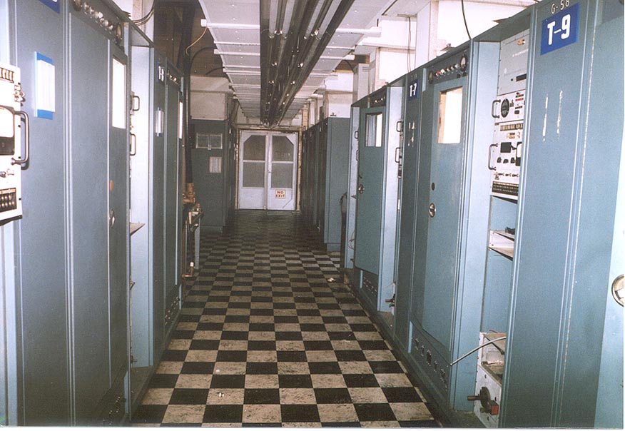
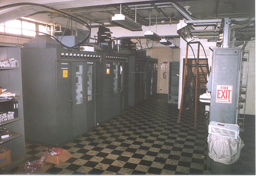
The issue of low morale is palpable and often present in conversations that address historical perspectives on a particular station closing, transfer of technologies around the network and any other such topics. Precipitated by the long periods of employment that are relatively standard in the Engineering area and perfectly understandable, this grieving process is a natural consequence of the pride involved in creating a state-of-the-art technical facility only to see it being dissected piece by piece as technology continues its relentless creative destruction.
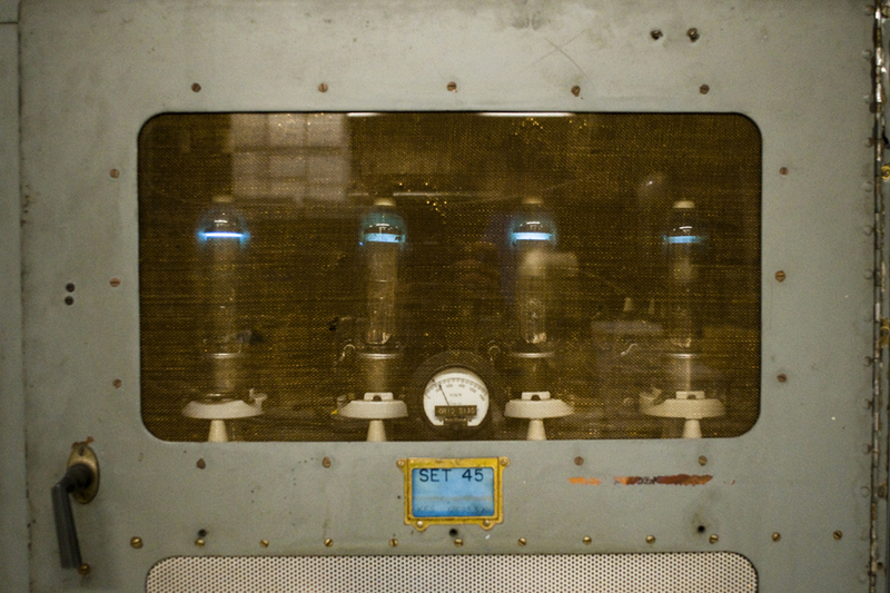
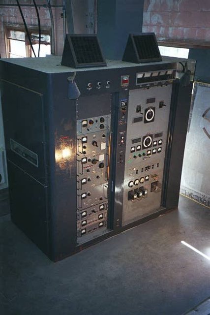
An interesting statement and it shines a light on several things heretofore unsaid in broadcast engineering. We love our transmitters, as strange as that may seem. We love our towers and antennas. Parting with something that has become an integral part of our working environment is difficult, to say the least. Watching something be signed off for the last time and then hauled to the scrap heap is very disheartening, especially if there is no replacement.
On the IT side, things are not so good either. The main concern is the infrastructure of the IT backbone. Several deficiencies are noted in the cabling and router; the cabling is in serious disarray and there is only one router for the facility. There is also other problems noted with personnel and lack of project management experience and/or IT department goals.
Overall, moving into new media fields makes sense. There are, however, many places where new media is unknown or at best, mostly unavailable. Moving content delivery from over-the-air broadcast to IP-based distribution may be far less expensive to operate, that is true. It is also far more susceptible to being disrupted by accident or design. In those areas where the internet is spotty, shortwave radios are abundant and relied upon. If the VOA is not on the air, then some other station will be.