Filtering for co-located FM transmitters

Well-sited FM transmitter locations usually want some height above average terrain. This means either a tall tower or a high hill or mountain. Once a site is developed, co-location of other FM transmitters often happens because sites are expensive to develop. A second station can save money by using existing facilities.

For all those newly permitted LPFM stations; pay attention. If you are going to be co-located at an existing FM broadcast site, you may need to do this too.

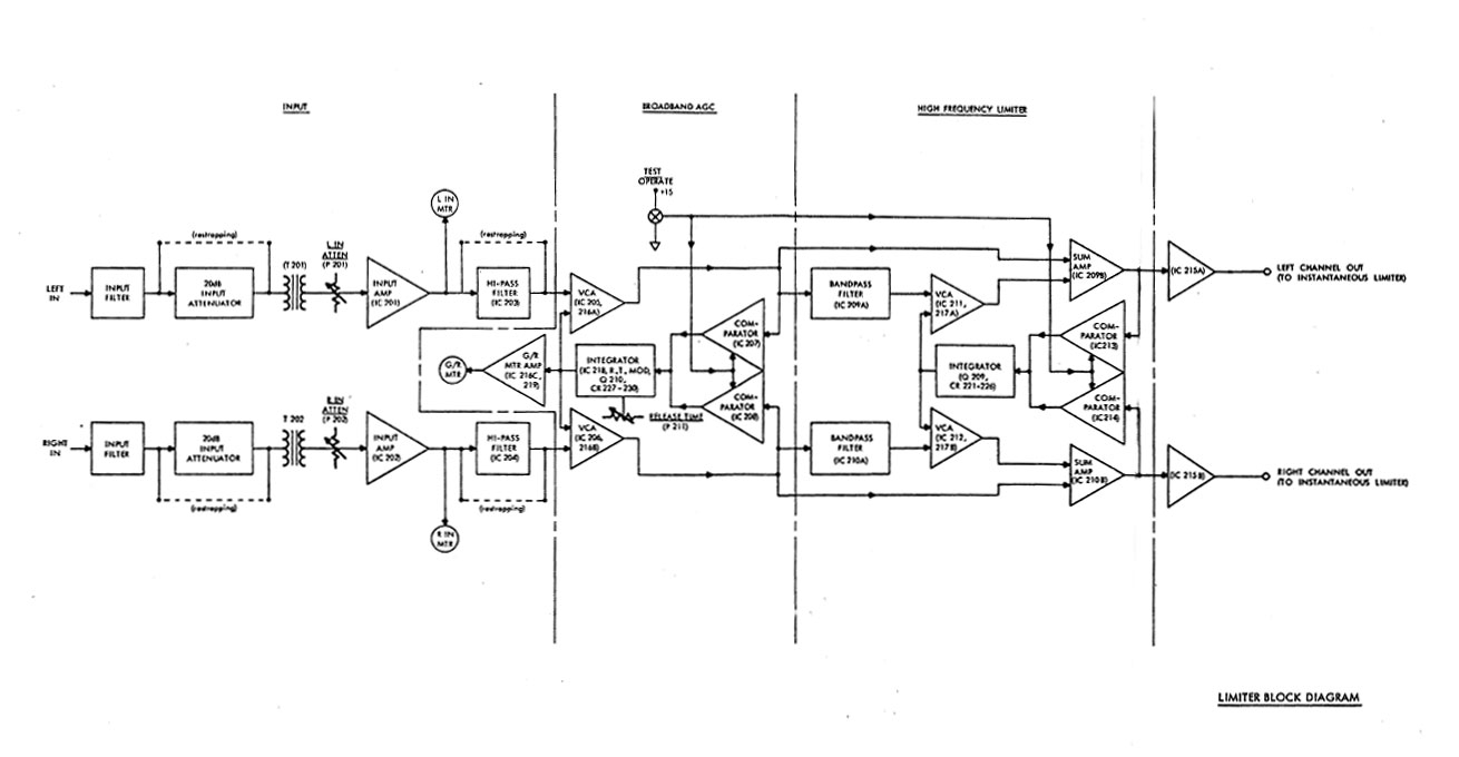
Interference from intermodulation mixing products can develop when FM transmitting antennas are in close proximity.  This is especially true with solid state, broadband PA commonly used in today’s VHF FM transmitters.  Thus, when antennas are closely placed, external filtering is required.

WUPE FM transmitter site, North Adams, MA

This is the case with a current project in North Adams, Massachusetts.  New England Public Radio is placing WNNI on the air from the WUPE-FM site.  WNNI is using one of those new Harris (now GatesAir?) Flexiva transmitters and WUPE-FM uses a Crown FM-2000A.  The antennas are on separate towers, but the towers are in very close proximity, about 30 feet apart.  In order to avoid any possible problems, a Shively 2602-3A-FB 3 pole filter was installed on each station.  The filter is a bandpass for the station installed and a notch for the other station.

The primary concern here is mixing products between the two transmitters.  Both have broadband solid-state amplifiers with low-pass filters before the output connector.  There are three frequencies of interest;

  1. (F1 – F2) + F1 or (100.1 MHz – 98.9 MHz ) + 100.1 MHz = 101.3 MHz
  2. F2 – (F1 – F2) or 98.9 MHz – (100.1MHz  – 98.9MHz) = 97.3 MHz
  3. F2 + F1 or 100.1 MHz + 98.9 MHz = 199 MHz

That, plus harmonic measurements out to three or four harmonics of the fundamental frequency should be enough to demonstrate compliance with FCC out-of-band emissions standards.

Measurements on these frequencies must meet the emissions standards outlined in FCC 73.317 (d), which states:

Any emission appearing on a frequency removed from the carrier by more than 600 kHz must be attenuated at least 43 + 10 Log10 (Power, in watts) dB below the level of the unmodulated carrier, or 80 dB, whichever is the lesser attenuation.

It is also noted that this site has several cellular carriers and no doubt has or will have LTE at some point. We all know that rural LTE installations can create self-induced problems, which are then conveniently blamed on the nearest broadcast station because, hey, why not?

To further complicate matters, New England Public Radio also has a translator, W266AW (101.1 MHz) on the same tower as WNNI.  The same measurements noted above must be repeated for the translator.

WNNI FM transmitter and Shively filter

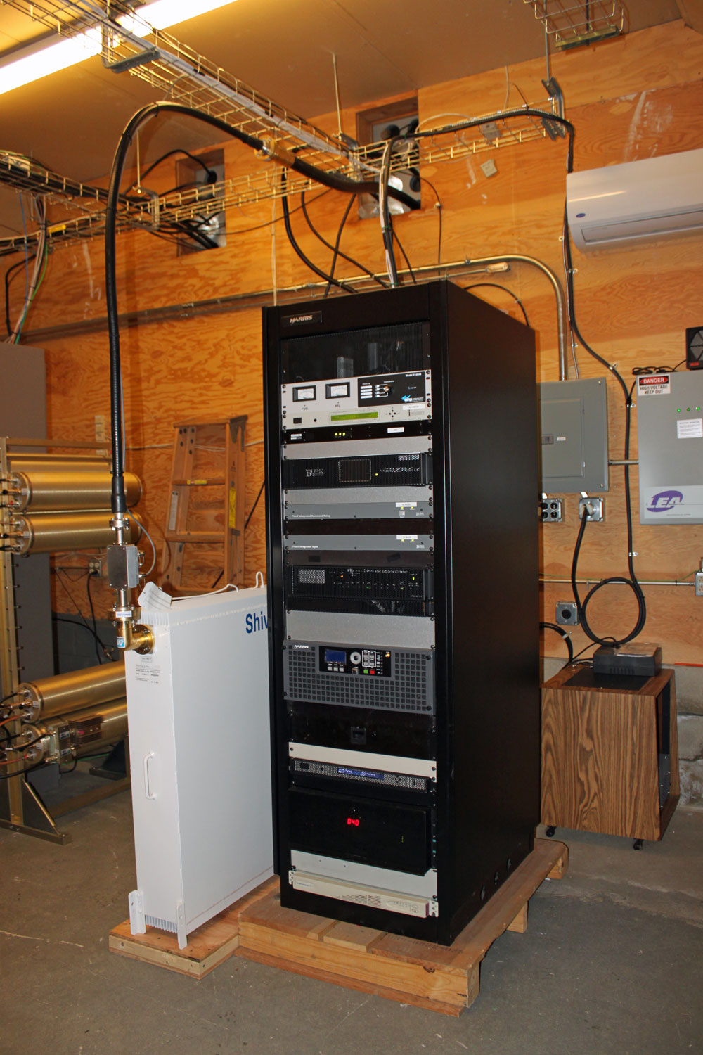
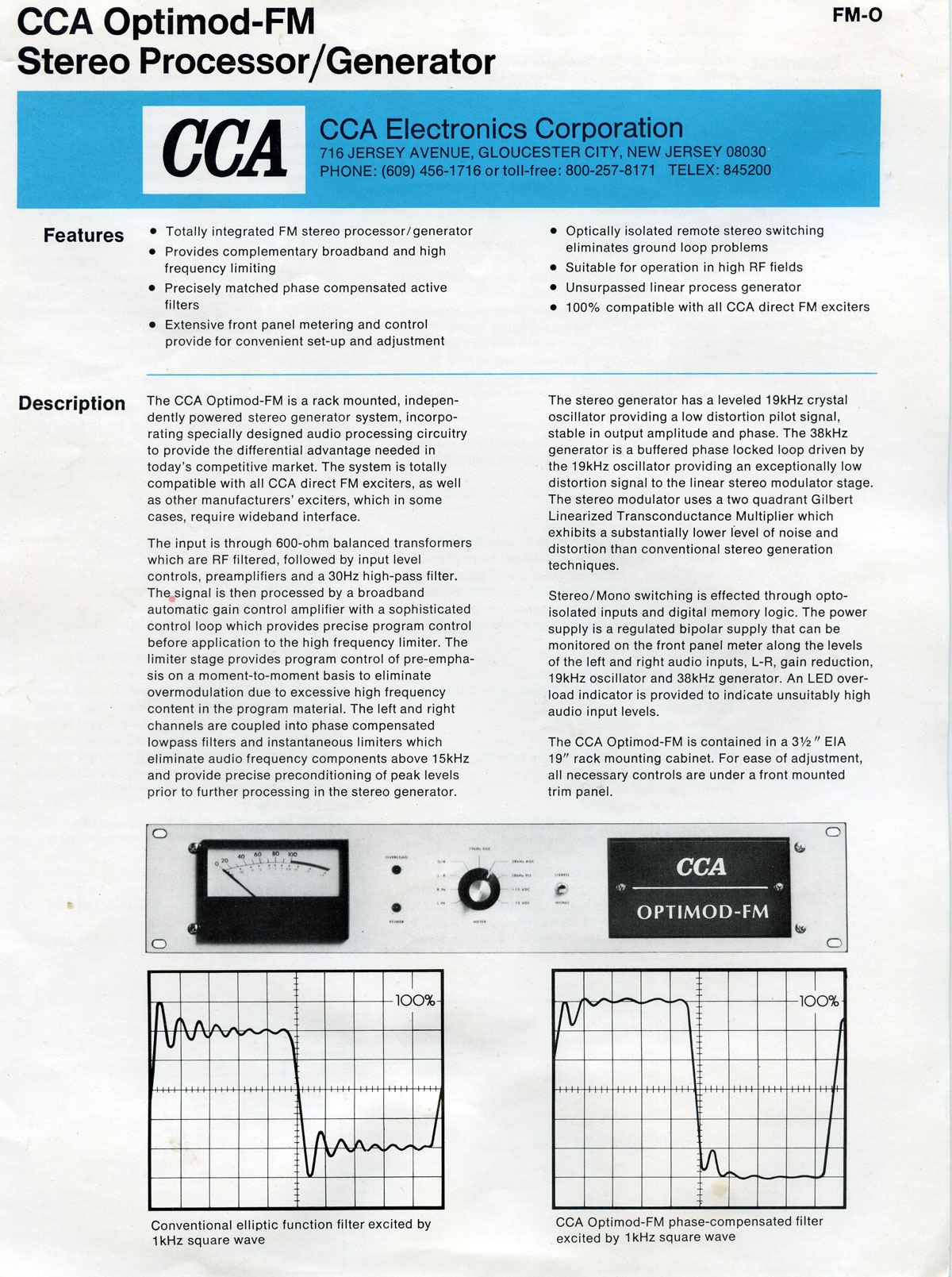
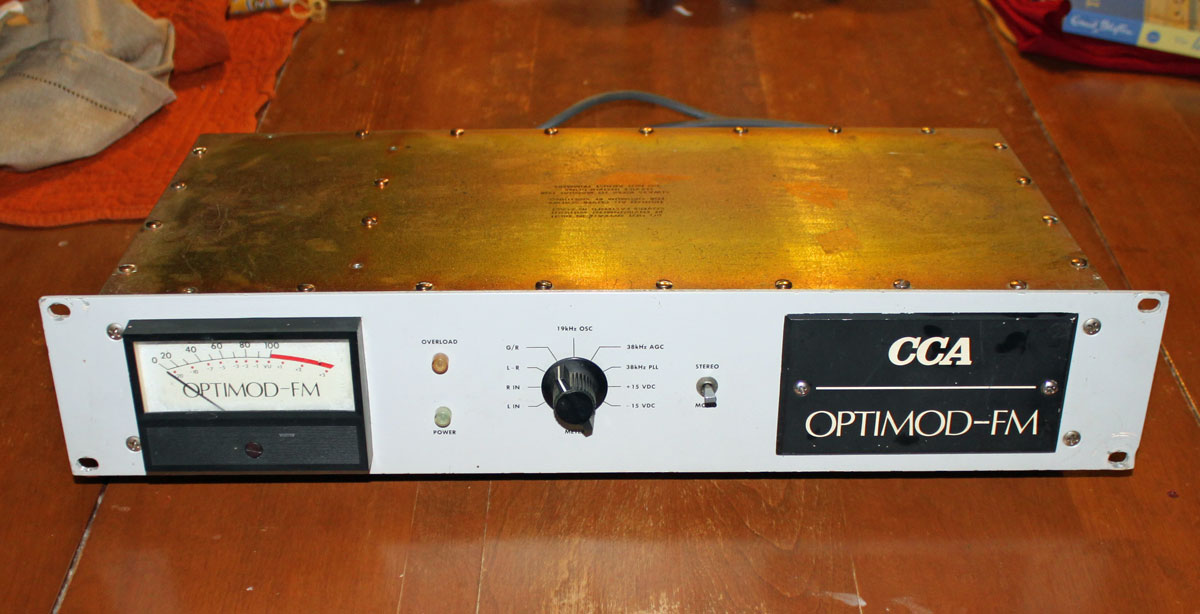
WNNI equipment rack.  This is one of those new Harris (GatesAir?) Flexiva FM transmitters.

WUPE-FM Shively Filter

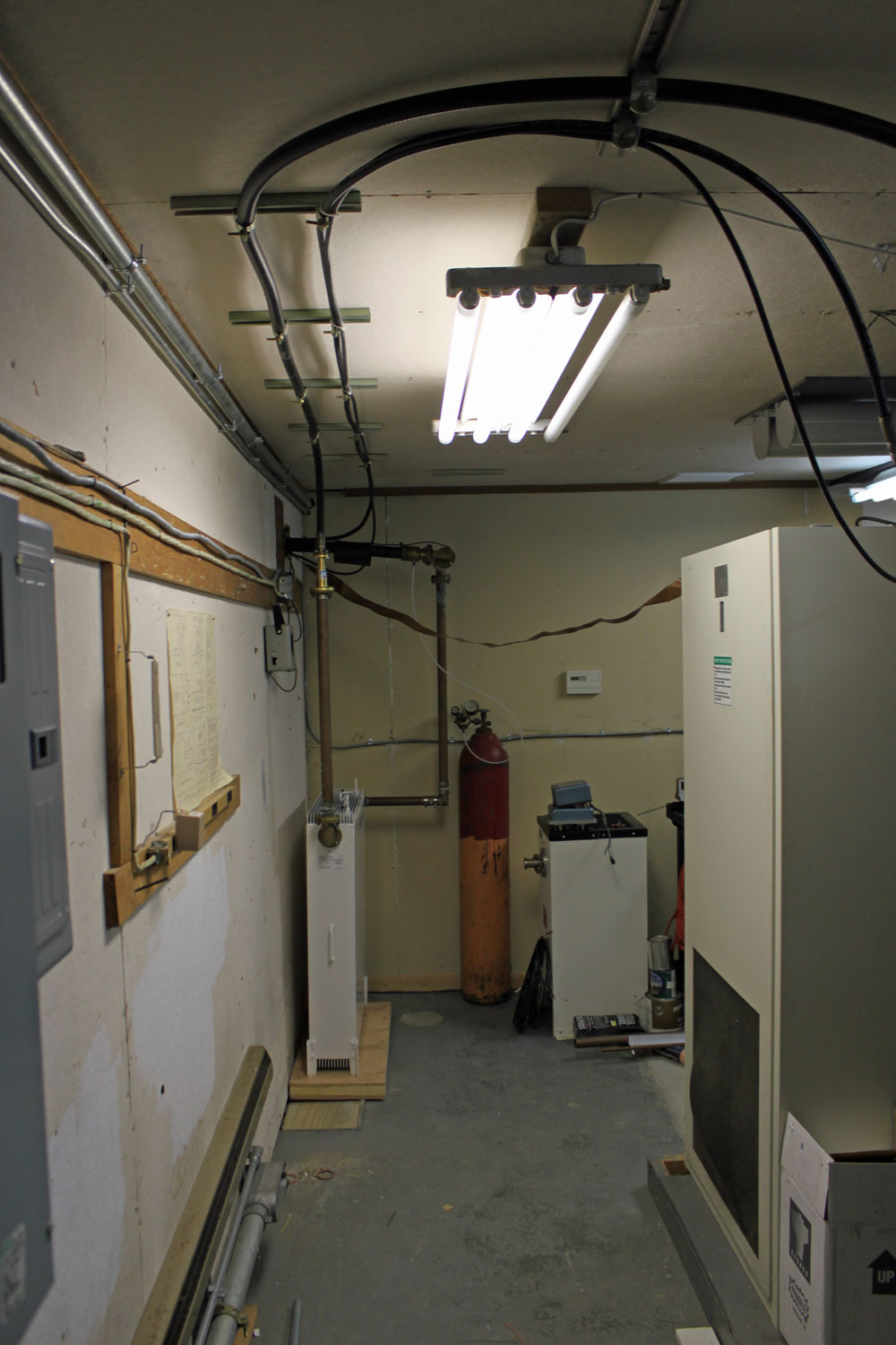
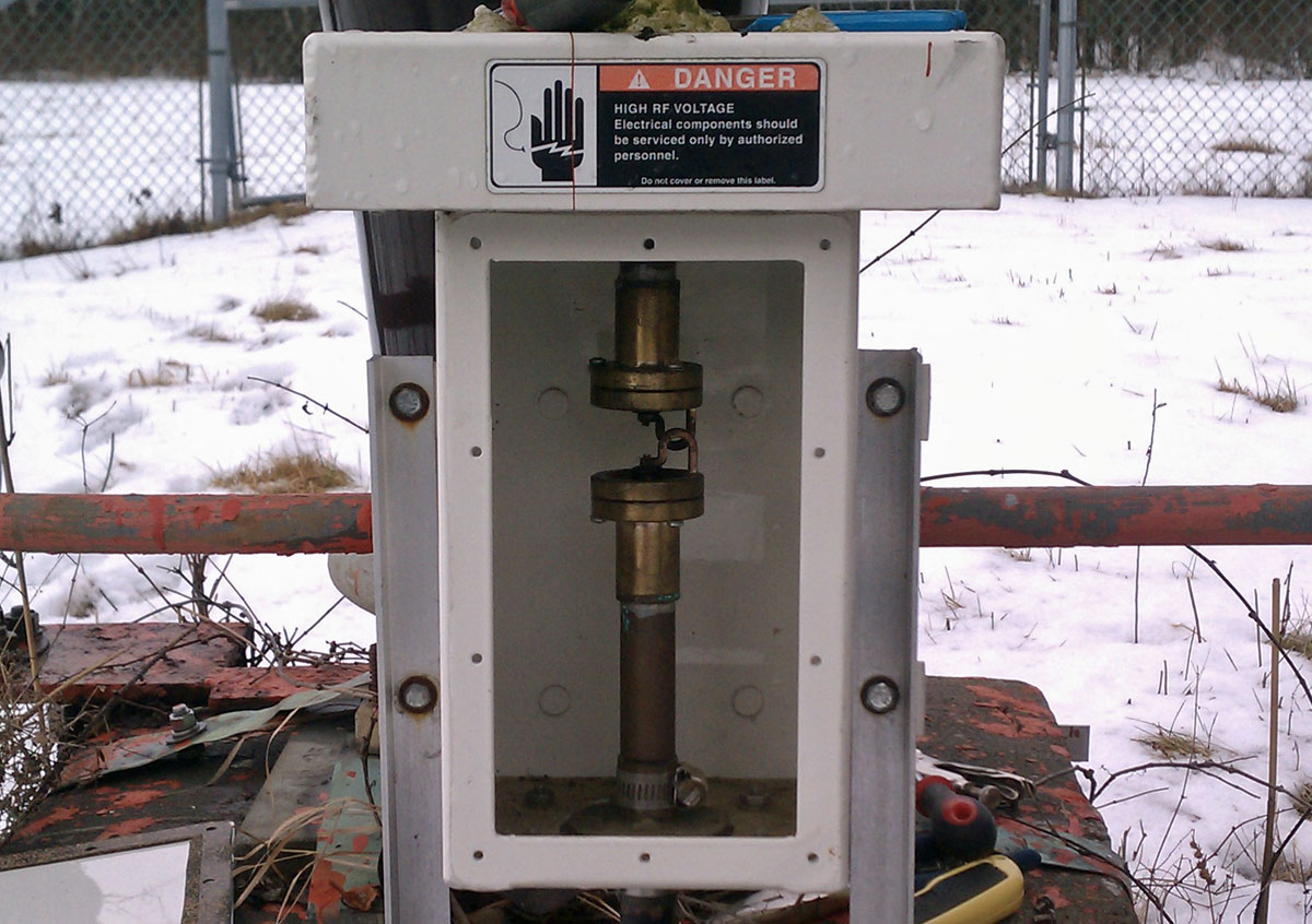
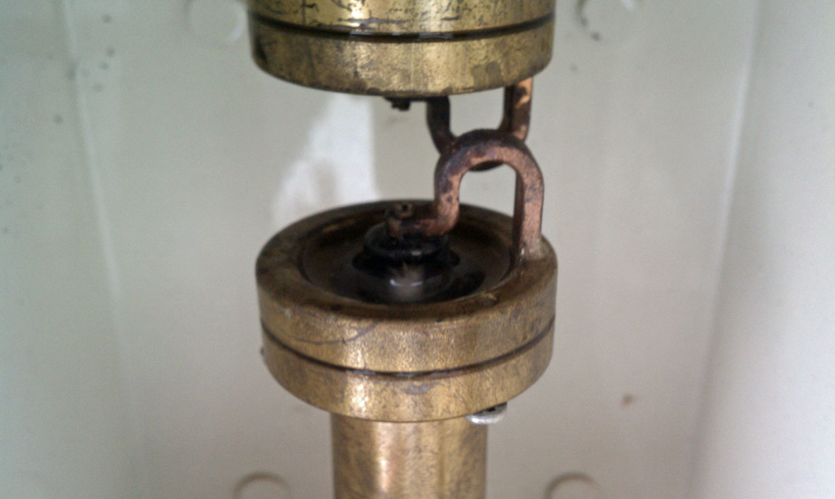
WUPE FM filter installation

wave spaced Shively antenna.  Antenna for W266AW below
WNNI 4 bay half wave spaced Shively antenna. Antenna for W266AW below

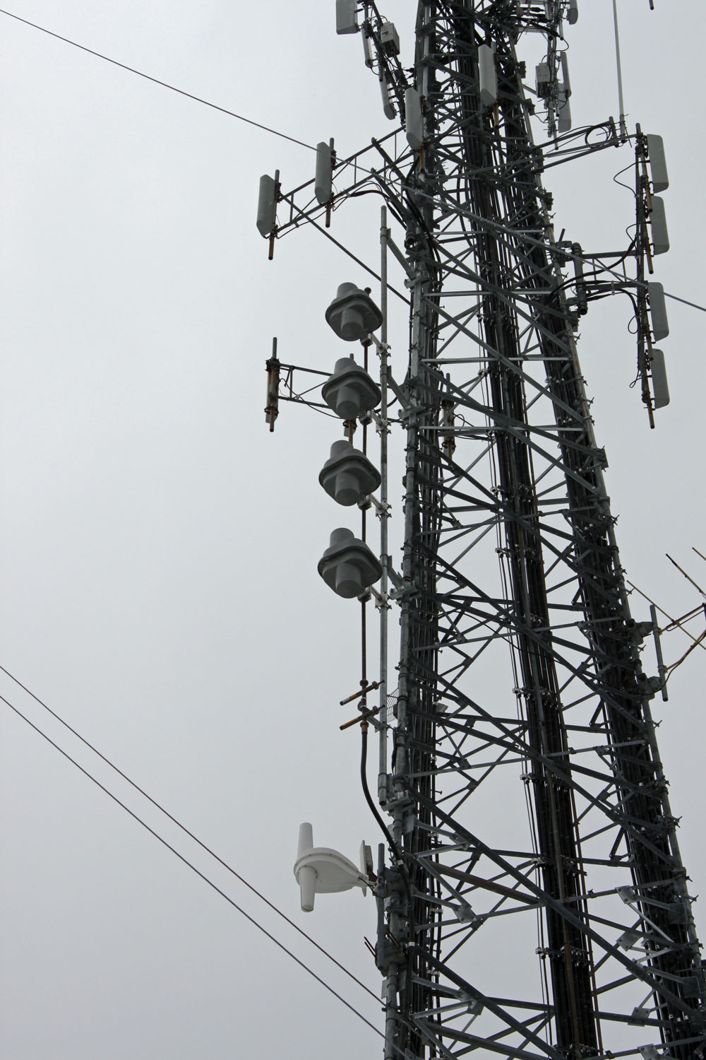
New WNNI antenna mounted on cell tower next to WUPE-FM tower. The W266AW translator antenna is directly below WNNI’s main antenna.

WUPE-FM 3 bay half wave spaced Shively antenna

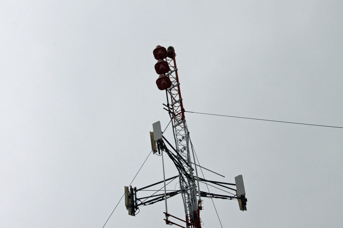
WUPE-FM antenna installed on the original broadcast tower.  I believe the tower dates from 1959 or so.

It is important to get this type of installation right the first time.  Creating interference all around or above the FM band is never a good strategy.  Going back to ask for more funds to make something right is also highly frowned upon.

The Kintronic Isocoupler

Had a problem with this Kintronic FMC-0.1 isocoupler the other morning.

Kintronic FMC-1.0 STL ioscoupler
Kintronic FMC-1.0 STL isocoupler

After an overnight drenching heavy rain and very high wind, the STL transmitter associated with this unit was having high VSWR faults.  This isocoupler crosses a base insulator of an AM 50 KW directional antenna.  This particular tower has negative impedance, which is to say, it sucks power out of the pattern and feeds it back to the phasor. An interesting discussion for another time, perhaps.

Using a dummy load, we isolated the problem to the isocoupler by first connecting the load to the output on top of the unit (the problem still exists) and then to the transmission line prior to the unit (the problem went away).  Of course, the AM station had to be taken off the air to do this work.

Once the issue was confirmed as the isocoupler, I opened the unit up and found that water had entered and pooled in the top of the bottom half of the isolation transformer.

Kintronic isocoupler transformer

The isolation transformer consists of two loops to ground capacitively coupled through air dielectric. The issue is with the opening around the top of the unit, under the lip of metal lid. Apparently, this allowed water in.

Kintronic isocoupler isolation transformer

It is difficult to tell with the lighting in this photograph, however, the bottom part of this isolation transformer has water pooled around the center insulator.  Using a rag, I cleaned out the water and dirt from the center insulator.  After reconnecting the antenna and transmitter transmission line, a quick check revealed the problem was much better, but still not completely gone.  I suspect water seeped further down into the bottom half of this unit.  The repair work was good enough, however, to return both stations to the air.

Glad to get that bit of work done while it was still relatively warm out.

Analog Sauce

A little blast from the past. This was found in a transmitter manual at one of the sites we take care of:

CCA Optomod 8000
CCA Optomod 8000

I thought I would scan it and make it available here.  As luck would have it, there is also a corresponding piece of equipment to go along with it.  I had never seen a “CCA Optomod” (.pdf) before I was working at one of the radio stations in Trenton, Florida.  This unit was rescued from under a pile of garbage out in the lawn shed.  It was full of mud wasp nests and mouse droppings.  Needless to say, it required a bit of TLC to return it to operation.  I replaced the electrolytics, cleaned it up, and ran some audio through it.  It is probably as good as the day it left the factory.  Bob Orban made some really good stuff in his day.

CCA Optomod 8000
CCA Optomod 8000

The original Optomod 8000 was an evolutionary design that made FM radio processing what it is today.  The idea of combining broadband limiter, AGC and stereo generator in one box was a radical departure from the norm.  The audio limiter functioned as a 15 KHz low pass filter and broadband AGC.

Orban Optomod 8000 audio limiter block diagram

The stereo generator used very modest amounts of composite clipping to reduce overshoot and transients. Many people disparage composite clippers. If done correctly, it is transparent to the listener and increases perceived loudness by stripping off modulation product that is non-productive.

Orban Optomod 8000 Stereo Generator block diagram

Some thirty five or so years later, there are still many of these units in service in various stations around the world.

Somewhere, a community has lost its radio station

I am sure that this has happened in more places than one. WZAD 97.3 MHz was licensed around 1990 as part of the 80-90 drop-ins.  The 80-90s were the beginning of the end for viable douopoly operations is smaller markets and triggered the huge wave of consolidation that began a few years later.  WZAD started out as a community-oriented station, with a free-form format.  DJs often brought their own records to the studio and spun anything from classic rock to jazz to disco or whatever.  As such, the station never really caught on.  Listeners would tune in to hear their favorite Led Zeppelin song but here “Ernie’s Classic Polka Show” instead.

A few years later, the station was sold to somebody that changed formats to a satellite oldies format.

The station was sold again and again and again before finally ending up with a major consolidator.

There is a lesson there for all the would-be LPFM applicants:  Nail down your programming ideas now, float ideas out among the community, and see what will work and what people are interested in.

This is the WZAD studio now:

WZAD studio, Wurtsboro, NY

When was the last time anyone from the station was here or set foot anywhere near the community of license?  The front lobby of the studio is full of garbage and an old dot matrix printer.  It looks like there has been a leak and all the ceiling tiles have fallen down.

The station is being programmed out of the Poughkeepsie studio cluster with an automated country format called “The Wolf.”  There is a live morning show, or at least there used to be, I don’t know anymore.  How is this station serving as a public trustee?