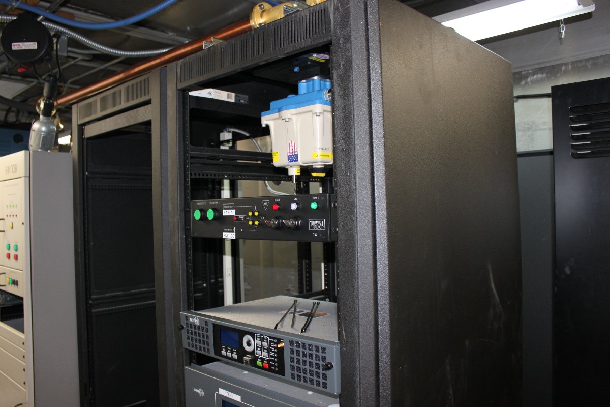
I was at the WEBE transmitter site recently and took the time to look over the transmitter we installed last year:
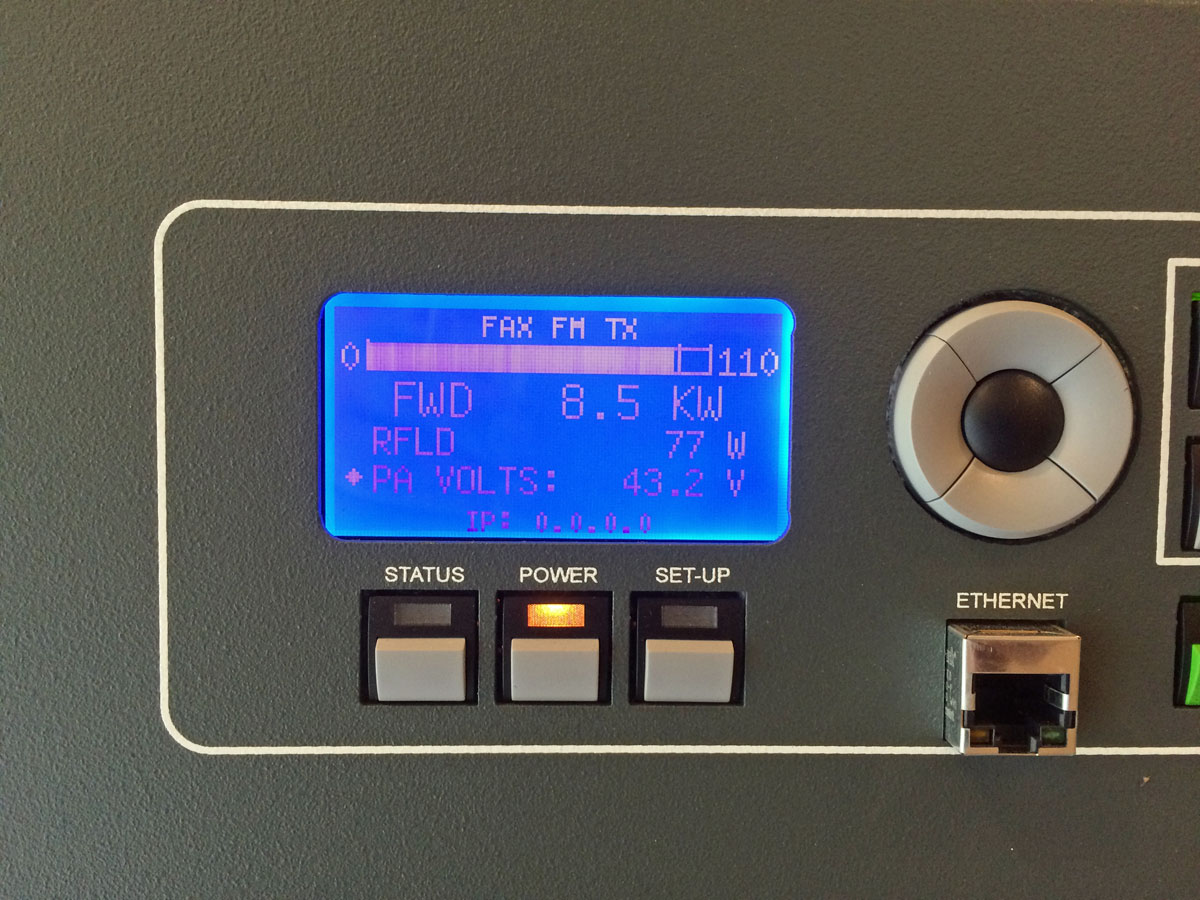
Overall, I would say that this transmitter has been very reliable. We had to install a UPS for the exciter and HD Radio exporter, but that is not a big deal. During the first power outage, the exciter went dark first. It took longer for the transmitter controller board to lose power, in the interim the controller turned the transmitter power all the way up. When the generator came online 10 seconds later, the transmitter returned to operation at 41.5 KW. This, in turn, caused one of the other field engineers to freak out and nearly lose his mind (stay away from the brown acid, FYI).
I installed the UPS a few days later.
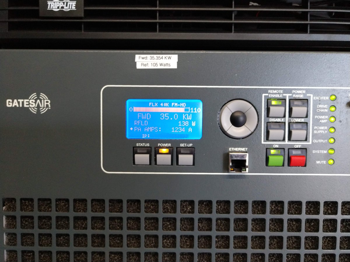
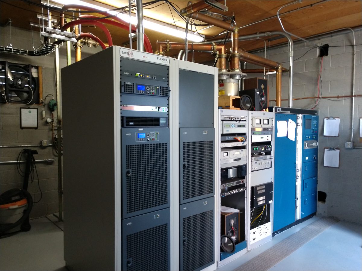
The transmitter power output is 35.3 KW, which is getting into the semi-serious range. The reflected power goes up when it gets warm out and goes down in colder weather. Over the winter, it was running about 50 watts. Even at 138 watts, that represents 0.004% reflected power. The TPO forward goes to the 6 bay, 1/2 wave spaced antenna side mounted, 470 feet (143 meters) AGL. The station covers pretty well.
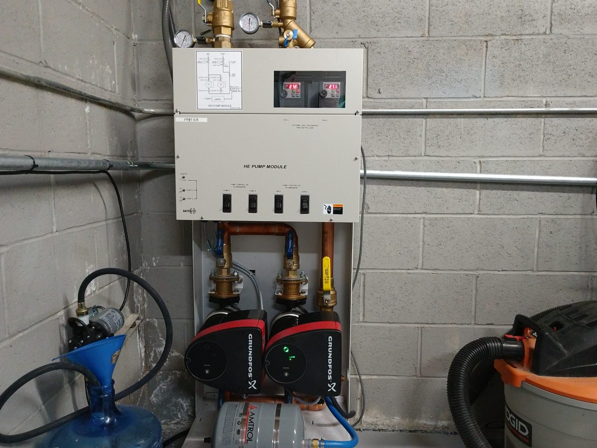
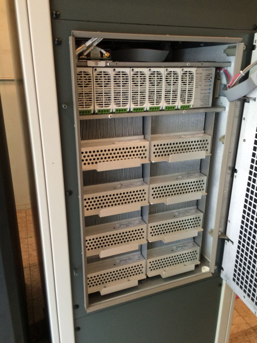
Overall, I would give the liquid cooling system an A grade. The transmitter still dumps a fair amount of heat into the room from the RF combiners and PA power supplies. Most of the heat, however, ends up outdoors. Previously, we had two Bard 5-ton AC units running almost full-time. Now, only one AC unit cycles on and off except for the hottest days of the year. The outside temperature when this picture was taken was 81 degrees F (27.2 C).
Next year, we will have to send a sample of the coolant to be analyzed.
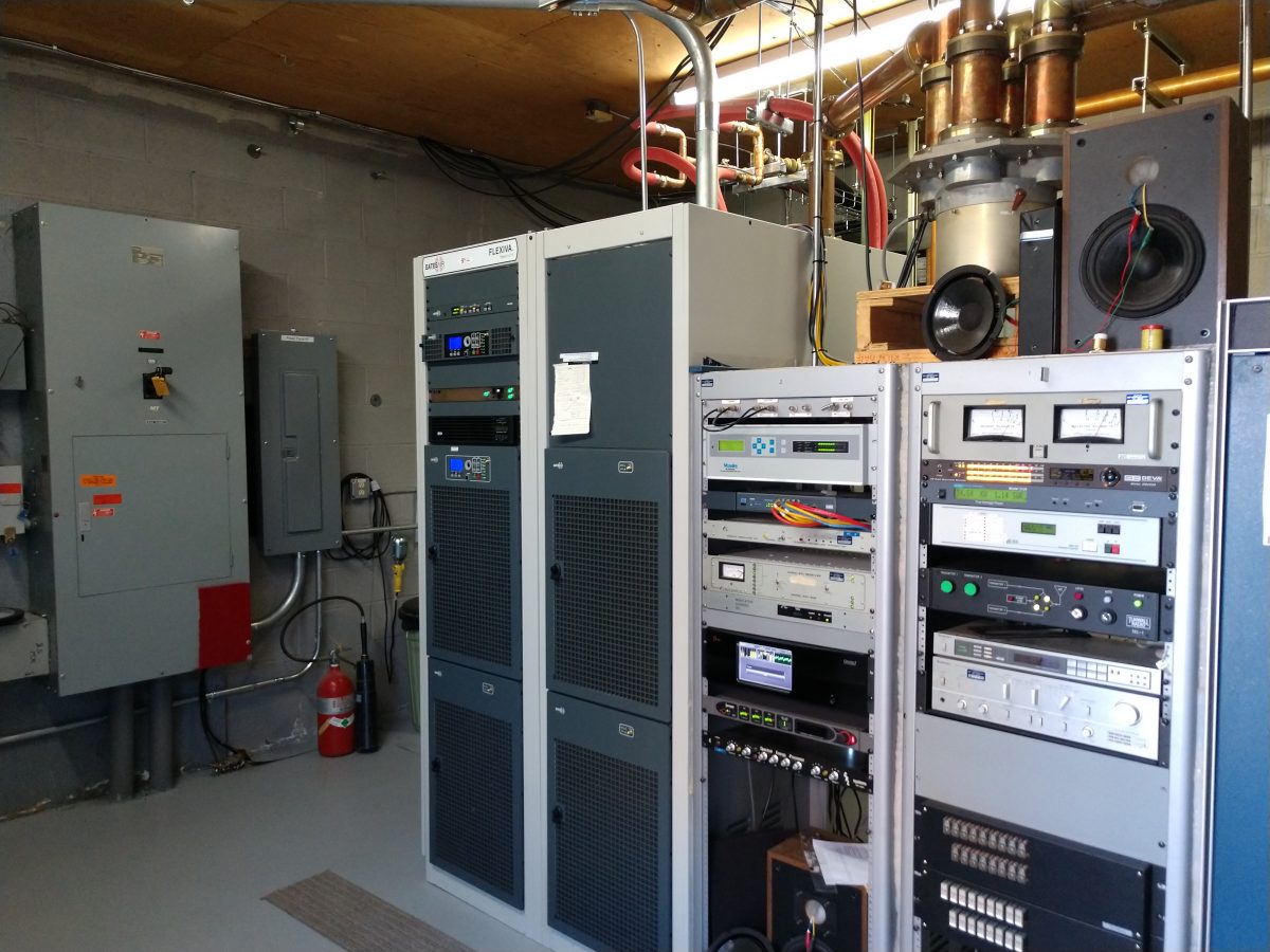
I have had good experiences with the GatesAir FLX/FAX series transmitters. I would recommend this to a friend.