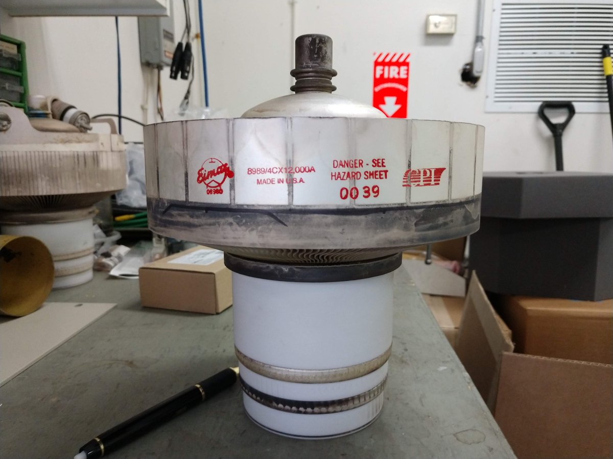
I do not know what the record is for the longest tube life, however, this particular tube lasted 17 years, 11 months, and 23 days. That’s 157,596 hours.
This was installed new in a Broadcast Electronics FM20T transmitter which was placed online on June 6, 2001. It lasted until May 28th, 2019 with almost no downtime. Towards the end, the emissions started dropping off and we increased the filament voltage up to 10 volts. When you have to increase the filament voltage, that really is the end for a tube.
The new tube was put in and I carefully marked out the date in the maintenance log. The hour meter on the transmitter stopped working several years ago.
Prior to this, the longest tube life I’d experienced was an EEV 4CX35000C from an MW-50B transmitter RF section. When that tube came out, it looked like it have been on fire.
Another install, this time a new BE product. I am familiar with the BE FM “C” series transmitter. Those are pretty solid units and we take care of many of them.
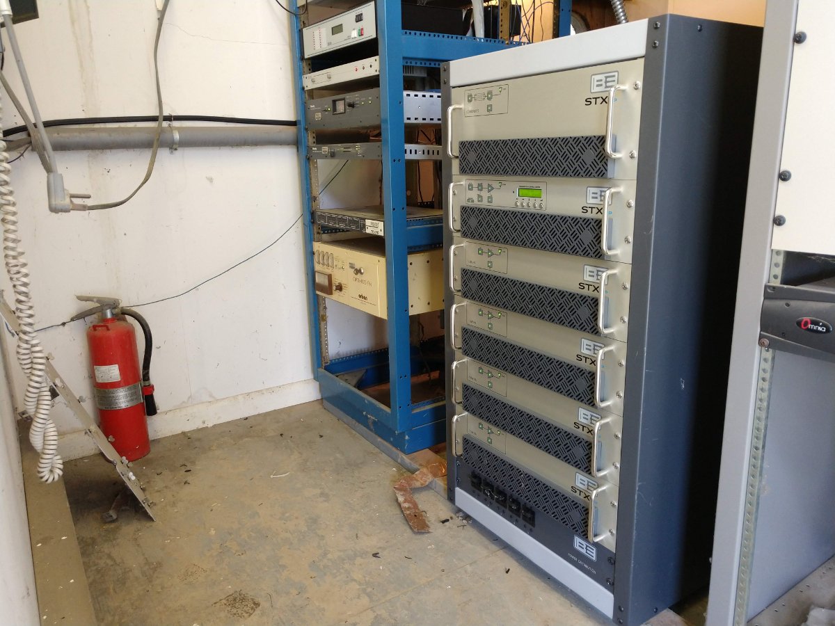
BE STX-5 LP transmitter
This new version of the transmitter looks like it has a little bit of Elenos in its DNA. Perhaps I am wrong about that.
The STXe exciter is an all-purpose analog/digital unit that will do standard FM stereo, hybrid FM +HD radio, HD radio only, DRM+, or FM and DRM+. I like that. It gives the owner lots of options with regard to future planning. Frankly, I would love to see some DRM+ testing done in the US.
We have actually installed a couple of “C” series transmitters with the STXe exciter as well.
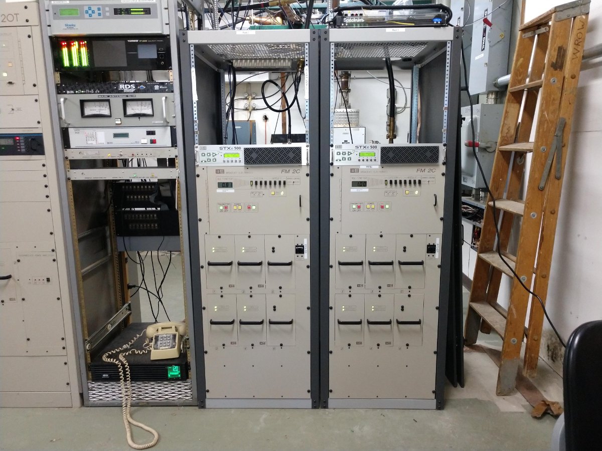
BE FM2C with STXe exciter
The rest of the transmitter consists of four RF amps and an output combiner all in a short rack. Frankly, if I were ordering one of these units, I’d order the taller rack. Not that I am getting old or anything like that, but stooping over to program the date/time, frequency, and power output introduced a slight discomfort in my lower back.
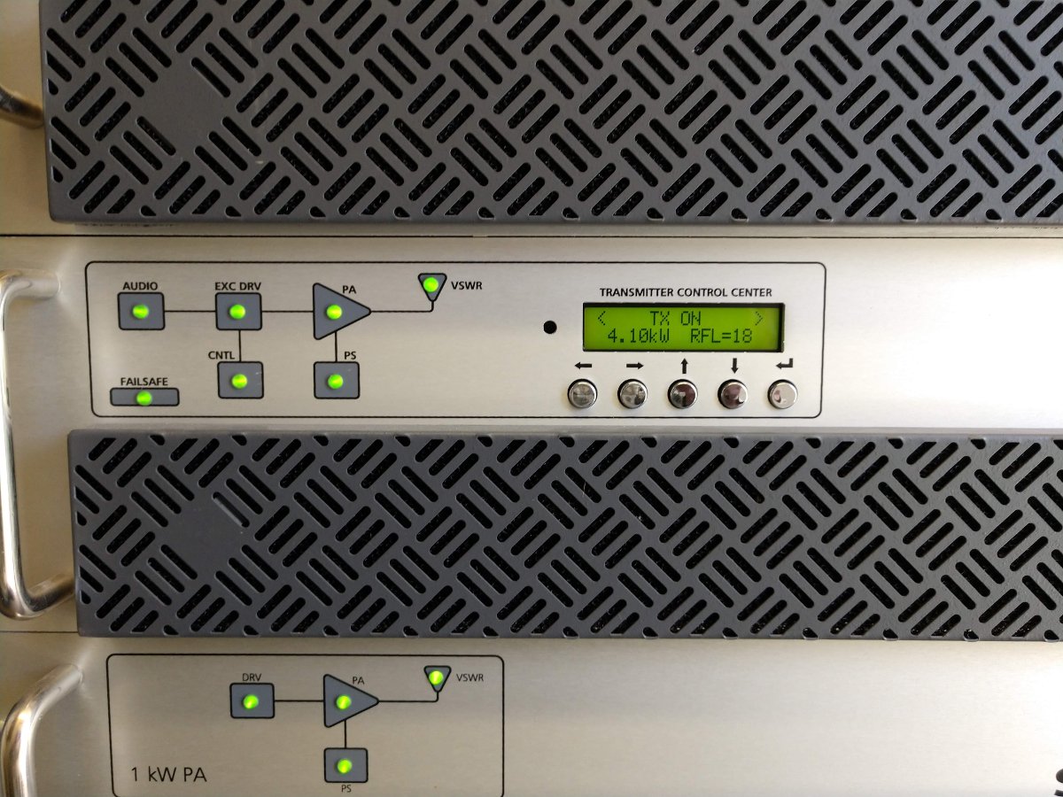
BE STX-5 LP controller/exciter
Running into the antenna. At 4.1 KW, 18 watts of reflected power is slightly high. This antenna has always had a little bit of reflected power.
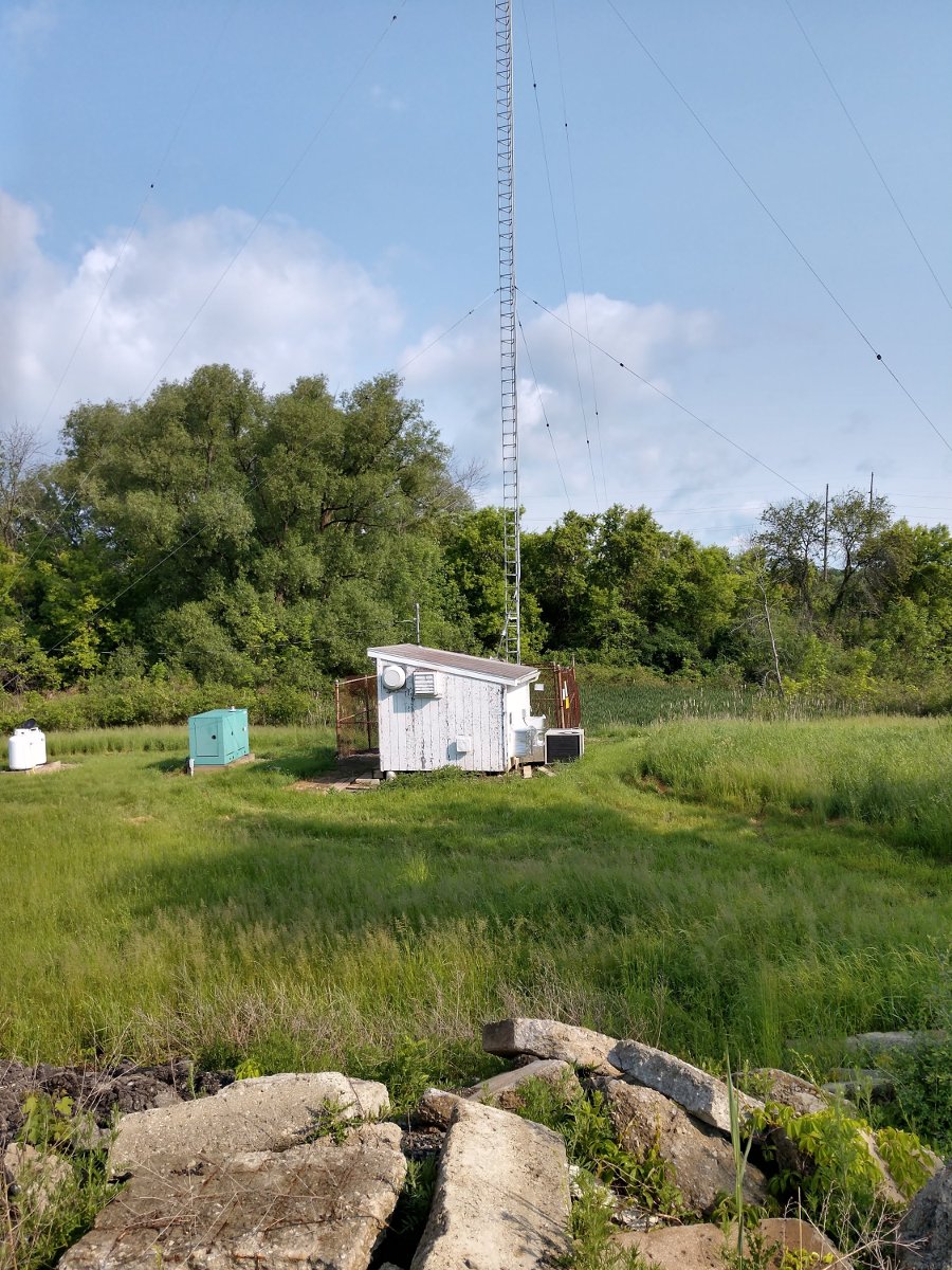
“The chicken coop,” WHUC and WZCR transmitter building
The building I installed this in is nicknamed “The Chicken Coop,” likely because it used to be an actual chicken coop. I am not kidding. The site was originally just the AM station (WHUC). That station had a different transmitter building located some distance away which was fed with open transmission line. This building was put in place sometime around 1969 when the FM station signed on as WHUC-FM (now WZCR). It has seen better days, but we are working on fixing some of the issues with air conditioning and cleanliness.
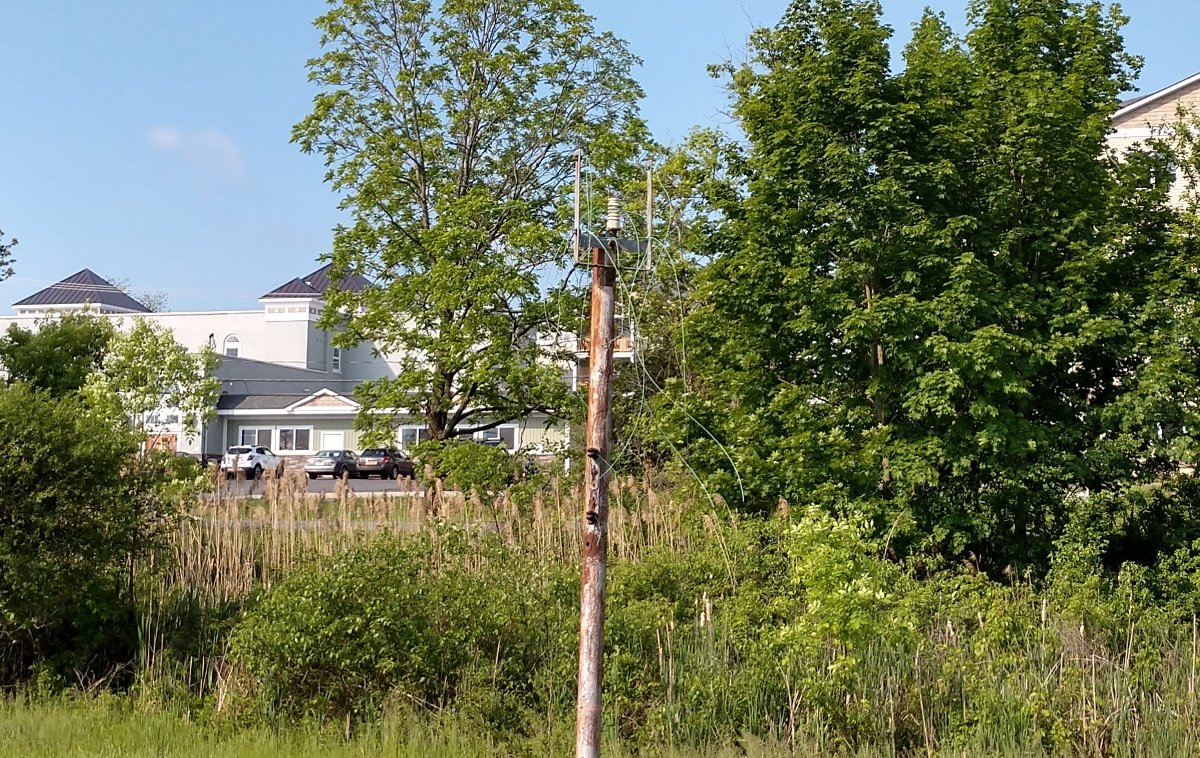
Remains of open wire transmission line left over from original 1947 installation
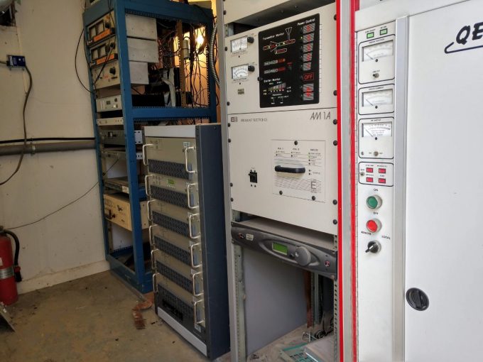
The transmitter fired up without any issues and sounds much, much better than the QEI which it replaced.
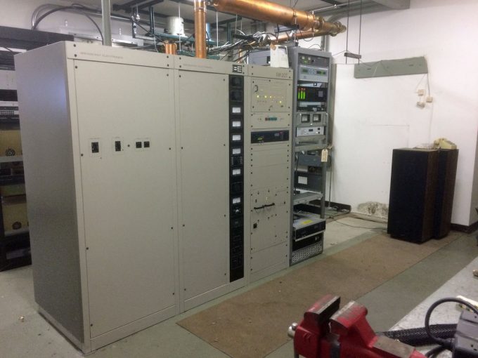
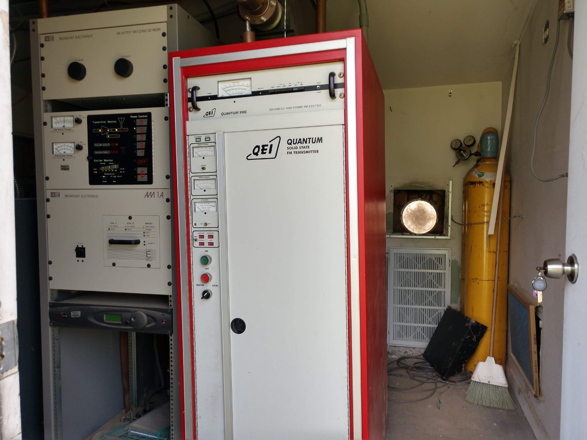
Tired old QEI transmitter
The QEI transmitter had problems over the years, mostly burned-out resistors in the RF combiner network. It has since been scrapped.
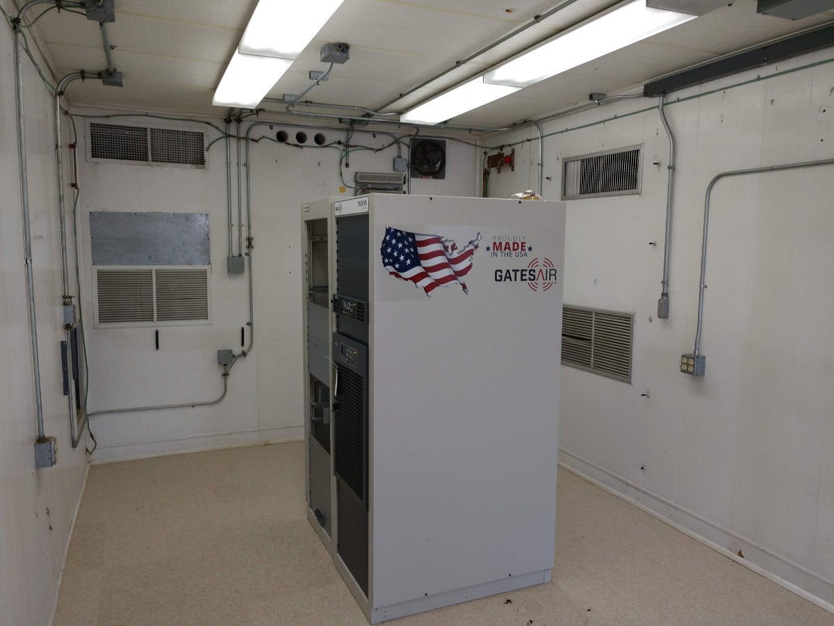
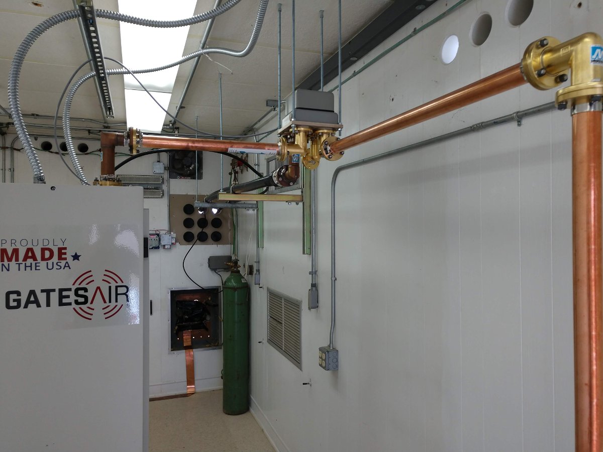
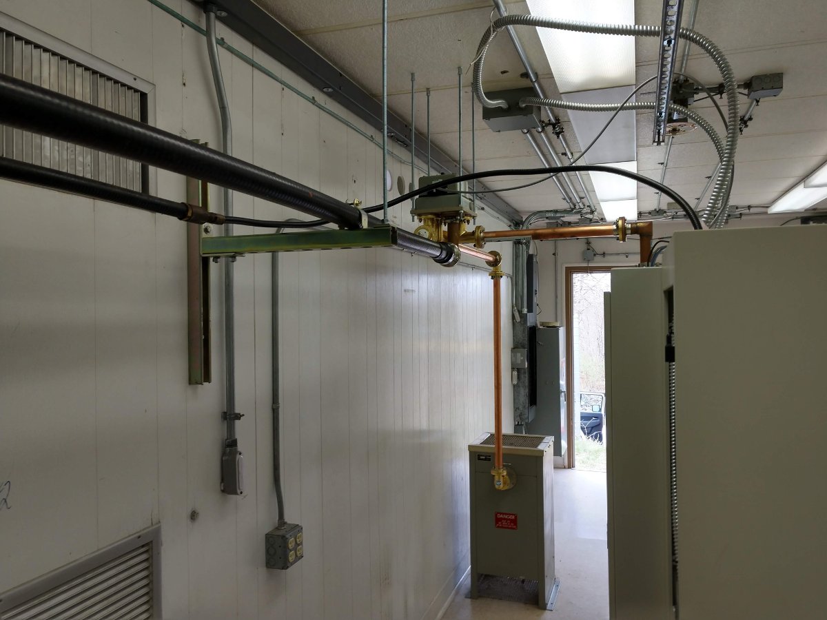
At the risk of becoming redundant, here are a few pictures of a GatesAir FAX-5 install recently completed in Westerly, RI. This was installed in a recently vacated Verizon cell site next to the old transmitter building. The old transmitter building and the equipment contained therein had seen better days, to be sure.
UPDATE:
As requested, the only pre-installation photo I can find:
Some Verizon equipment still in place
That photo was taken back in October 2018, when we first looked at the Verizon shelter as a viable alternative to the current transmitter site.
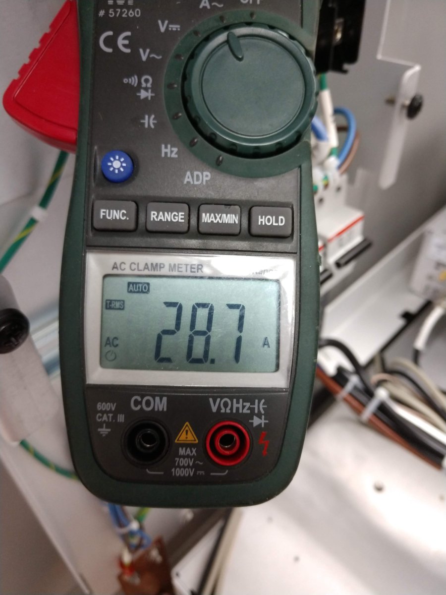
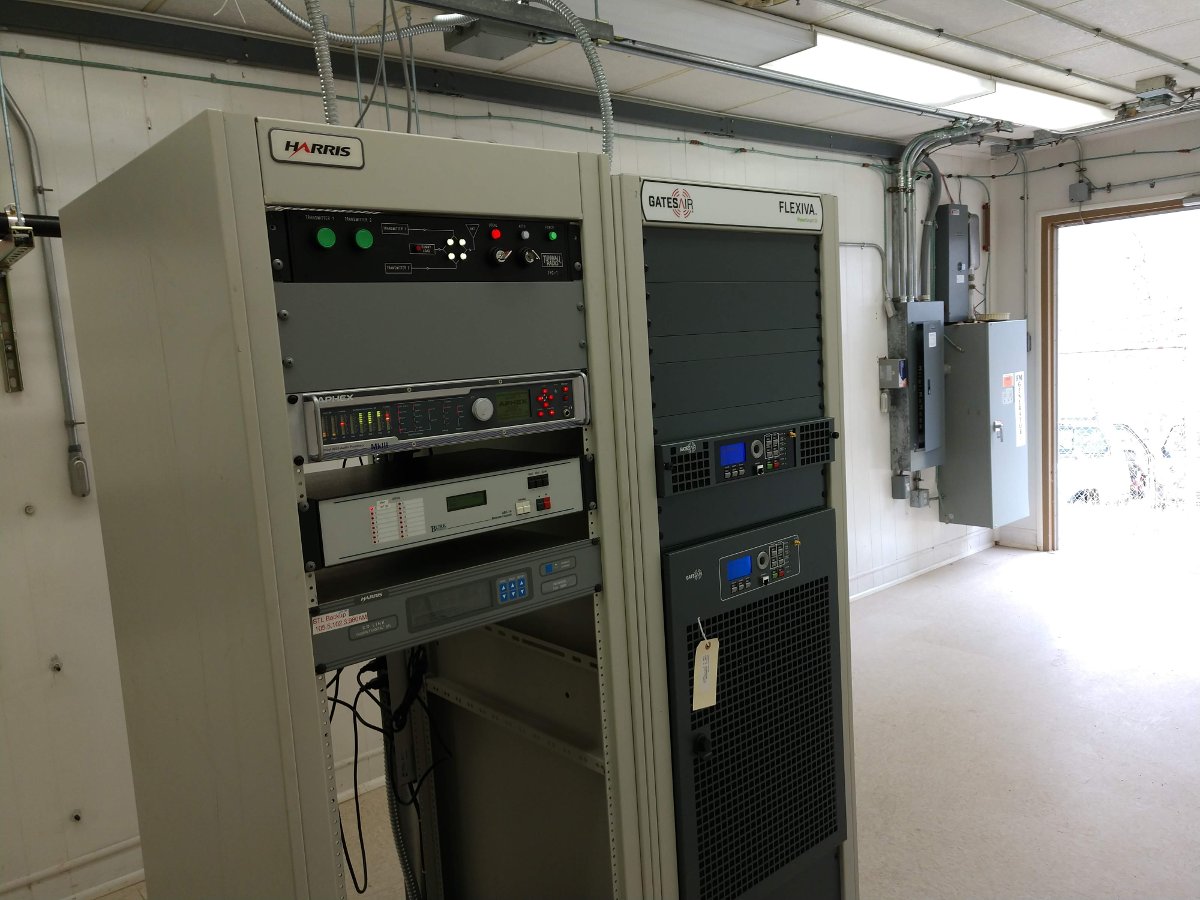
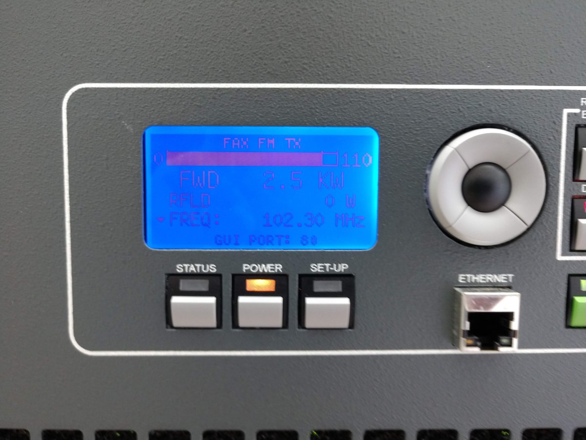
FAX-5 transmitter with fancy logo, placed in positionTransmitter in place, AC mains and RF connections madeGround strap installationTest mode, clamp-on AC current meter, measuring amps per leg at full powerFAX-5 transmitter and equipment rack, on the airTransmission line, supported by unistrutDelta coax switch and Electro impulse dummy load, salvaged from old installationFAX-5 running into antenna for the first time
Overall, the transmitter sounds great. Much better than the old unit which had an AM noise problem.
If it wasn’t so far away, this would have been a pretty easy project. There were minor miscues along the way that added up. I will say that I learned a few good life lessons about the reliability and responsibility of people.
Bad weather or other disasters can strike any time of year. Around these parts, the most dangerous weather events occur from early spring through late summer. In the past twenty years or so, we have had tornadoes, hurricanes, micro bursts, flooding events and so on. All of that got me thinking about what would happen if a tower came down, or a transmitter building was destroyed by fire, wind, water, etc.
If past events can predict future performance, there would ensue a mad scramble to replace damaged equipment and or get some type of temporary antenna into service. That is what happened in great City of North Adams, Massachusetts when the tower that held the cell carriers, the 911 dispatch, and the local FM radio station came down in an ice storm. Fortunately, we had a single bay Shively antenna at the shop that we trimmed up and installed on a temporary pole with 200 watts TPO.
That will cover the city of license, provided there is electricity…
What if there where an event that was so devastating that the electrical power would not be restored for months? Think about hurricane Maria in Puerto Rico. After that event, the infrastructure was so devastated that there was not even the possibility of getting a fuel truck to deliver diesel for the emergency generators at the hospital in San Juan. It can happen.
With that in mind, I began poking around and thinking about how I would get something back on the air. In the face of massive disasters, AM and FM radio is still the most effective way to communicate with the general public. Radios are still ubiquitous in homes, cars and businesses.
Bext 30 Watt FM exciter
In a short period of time I came up with a couple of solutions. First, the frequency agile Bext exciter uses a single solid state rectifier feeding 24 volts to the power supply board. The audio input includes a mono balanced line level input which can be fed by a computer sound card or some other simple source.
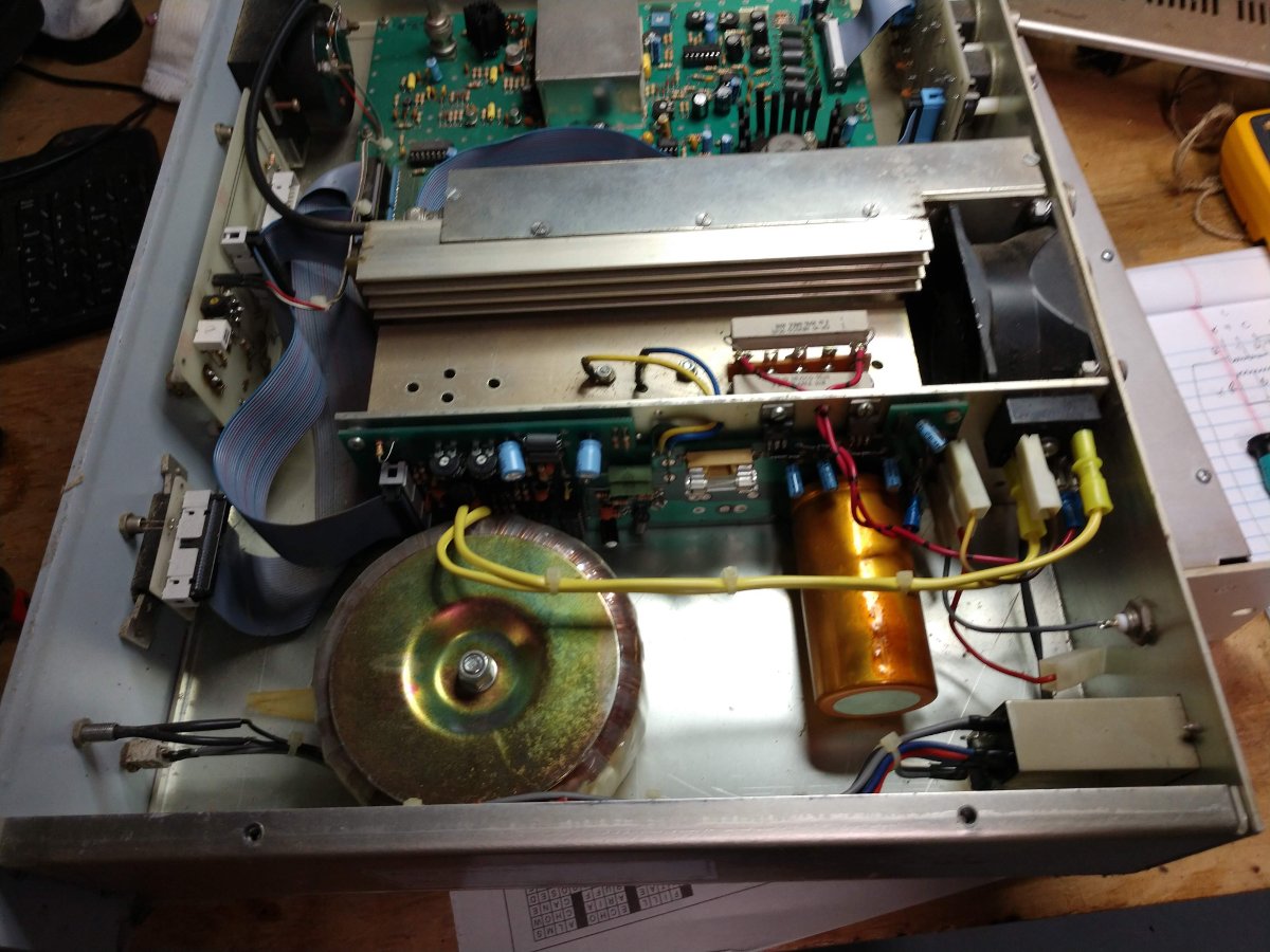
Bext 30 Watt FM exciter power supply
From there +12, +15 and +20 VDC are created to run various circuits. The heat sink cooling fan is the only thing that runs on 120 VAC, which is old and I might replace with a 24 VDC unit.
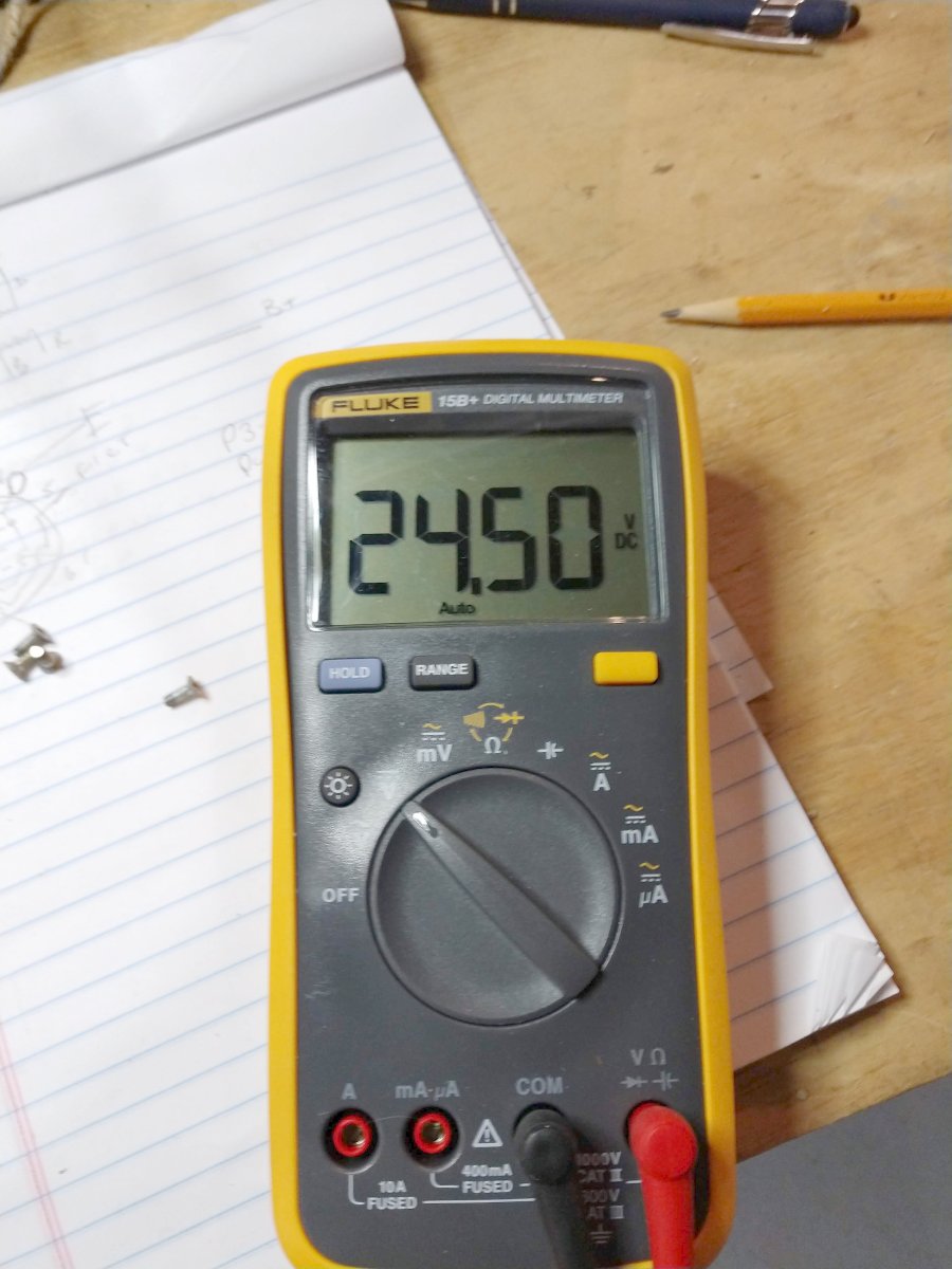
Bext 30 Watt exciter power supply voltage
The power output is about 22 watts, which is not bad. That will certainly get out well enough from a high spot and provide good coverage when the power is out because all the other in band RF noise generators will be off.
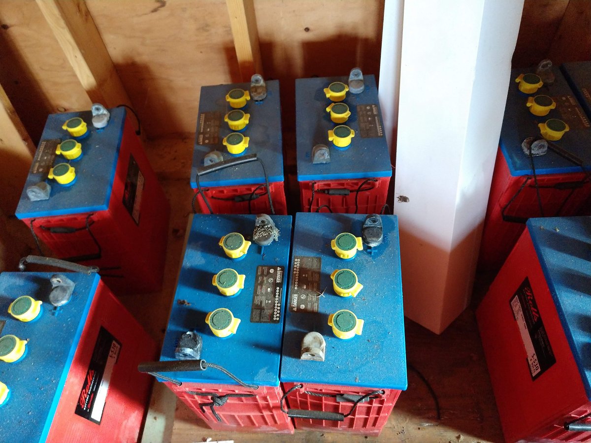
6 volt, 435 Ah batteries
Then I though about the deep cycle batteries in my barn. These 6 volt, 435 Ah units have been around for a couple of years, but last I checked, they still held a charge. Other deep cycle batteries from things like golf carts, fork lifts, campers, boats etc could also be pressed into service. The point is, 24 VDC should not be impossible to create.
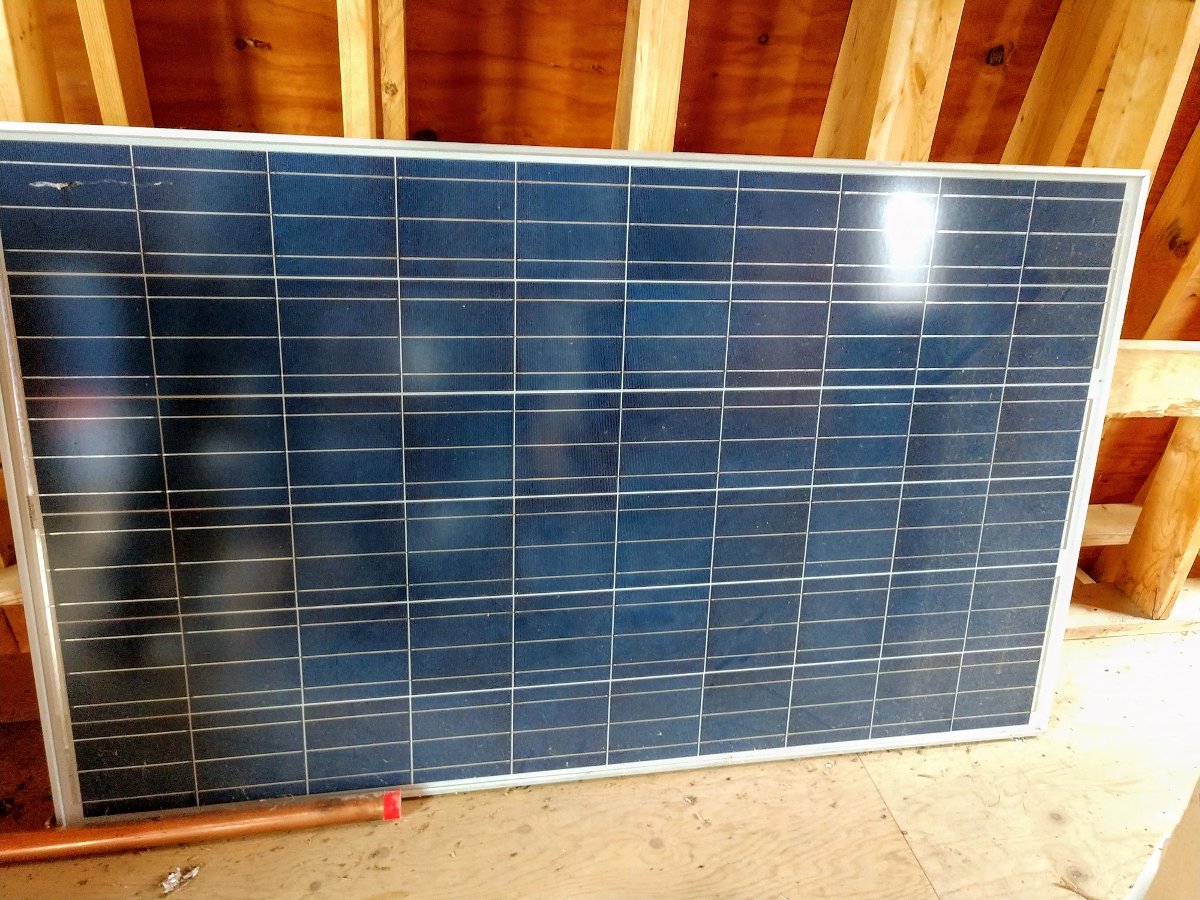
To keep a charge on the batteries, this solar panel will work:
225 Watt, 36 volt solar panel
This setup would require some sort of 24 volt DC charge controller, which I found on Amazon for less than $15.00 US. This charge controller has selectable 24/12 VDC output and also has two USB ports which would be handy for charging hand held devices.
I measured the power draw while the exciter was running 20 watts into a dummy load, it draws 120 Watts.
The final part would be some sort of antenna with transmission line. For this situation, a simple wire center fed dipole hung vertically would work well. This can be fabricated with two pieces of copper wire and a few insulators.
Simple dipole antenna
The lengths of each wire can be calculated as follows:
Approximate length in feet: 234/f (MHz)
Approximate length in inches: 2808/ f (MHz)
Approximate length in cm: 7132/f (MHz)
For the FM band, maximum length of wires needed will be 32 inches (81 cm). Insulators can be made of anything that does not conduct RF; PVC, ABS, dry wood, dry poly rope, etc.
Emergency FM band dipole, cut to 88 MHz, lowest FM frequency
I recommend to cut the wires slightly long, then trim little bits off of each end while watching the reflected power meter on the exciter. To keep RF from coming back down the shield of the transmission line, make 8-10 turns, 6-8 inches in diameter of coax as close to the antenna as possible and secure with a wire tie. This will create a balun of sorts.
My emergency FM kit consists of:
Bext Frequency agile exciter
30 feet, RG-8 coax with N male connector on one end
4 ten foot RG-58 BNC male jumpers
1 four foot LMR-400 N male jumper
Dipole antenna, cut long
Solar charge controller
Small basic tool kit; hand tools, plus DVM and soldering iron
Power cords, extension cords
300 watt 12VDC to 120VAC inverter (pure sine wave)
20 feet audio wire
Various audio connectors; spade lugs, XLR male and female, RCA, 1/4 TRS, etc
Various RF connectors; PL-259, N, BNC, etc
Bag of 12 inch wire ties
3 rolls of 3M Scotch 88 electrical tape
100 feet of 3/8 inch poly rope
This is all kept in a sturdy plastic storage bin from the Home Depot. If needed, the batteries and solar panel are stored in the barn along with an assortment of other goodies.
Will it ever be needed? Well, I hope not. However, it is much better to be prepared to restore services than wait for somebody to show up and help. Sitting around complaining about the government does not relieve those people in need during and after a disaster.