The Harris Z6HD transmitter

These transmitters are good.   They seem to behave in a mostly normal manner, having a few quirks now and then. This particular unit is installed at WFAS-FM in White Plains NY.

Harrsi Z6HD transmitter, WFAS-FM, White Plains, NY

I believe the reason for the installation was for the HD Radio® that was in it.  The Deathstar HD Radio® exciter is in the next rack over.  No further comment is needed.

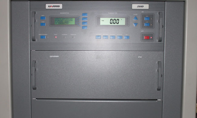
On this day, the transmitter had given up, throwing a main fan fault.  The fan (blower) motor had been replaced in the last six months (on a transmitter that is only five years old), so it was not that.  As it turns out, the stock fuses; 10 amp, slow blow, were just a little bit underrated for the job.  Harris released a service bulletin a few years ago calling for 15 amp slow blow fuses as replacements.  In any case, it was an easy fix and now there is a box of 15 amp slow blow fuses in the transmitter next to the fuse holders.

Harris Z6HD transmitter front RF modules

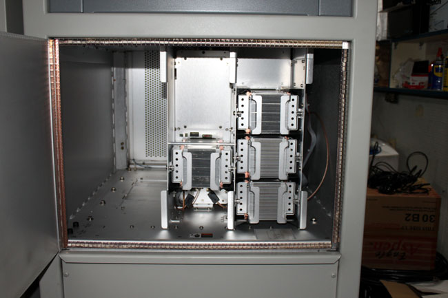
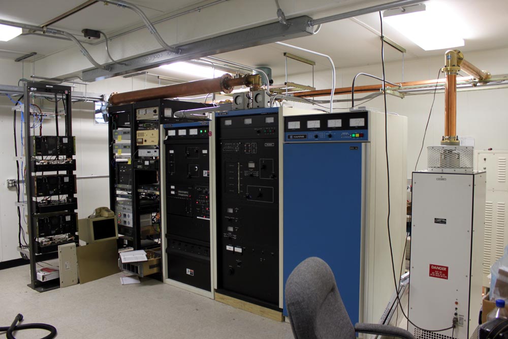
The modules are accessible by the front and rear of the transmitter.  These doors can be opened with the unit on the air since all of the high voltage is in the bottom of the transmitter where the blower is located.

The module in the middle is the IPA.  Each module has two RF amps, and each RF amp has two devices (BLF-177).  The devices are field replaceable, however, on the HD models, one has to make sure that the amplifiers are still linear.  On the non-HD models (Z6CD), this is not a problem at all.  Shorted MOSFETS will be noted by a fault of one entire power supply.  Removing the bad RF module will allow the transmitter to run at somewhat reduced power.  Finding the bad module may take a bit of trial and error.

Harris Z6HD transmitter back

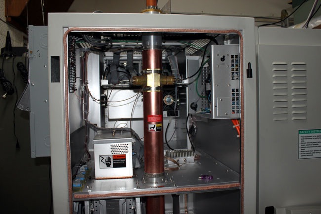
The back of the transmitter has the directional coupler, low pass filter, access to the back of the analog exciter, controller, and remote control connection points.

The power supply at the bottom of the transmitter has multiple taps, each one with its own fuse.  These can be a bit of a chore to work on.  There is also a ribbon cable that goes from the controller to the power supply board.  This is directly in the path of the cooling fan and can flop around causing the conductors in the cable to break.  The result is the power supply may not come on or may show an unbalanced power supply condition (in the case of a three-phase transmitter).  Very difficult to diagnose.

Harris Z6HD transmitter, on air, WFAS-FM, White Plains, NY

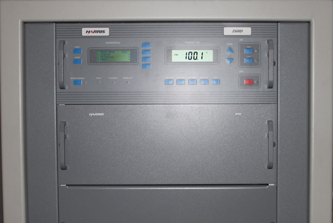
Here it is, running again.

The hard restart

Sometimes there is just no way around it, especially with some modern equipment:

Hard restart, Nautel VS2500 transmitter

This Nautel VS2500 transmitter got all cranky after lightning struck the tower (or nearby) on Friday night.  Thunderstorms in February are not unheard of, but they are unusual, at least in the Northeastern United States.

Nautel VS2500 FM transmitter, WBEC-FM, Pittsfield, MA

Anyway, the transmitter would not reset or restart via remote control, therefore, we had to ride the chair lift to the top of the hill and pull the plug to reset its logic and start over again.

Bousquet Ski Area Chair lift

At least the trip up to the transmitter site was scenic.  We had to wait a day for the winds to calm down, but all in all, not a terrible day.  Did I mention the scenery?

Work Ethic

We have this guy that works for us who is atypical. We call him Pete because that is his name.  The other day, he was slacking off on the job again, this time figuring out how to take a nap in a transmitter:

Pete working on a Harris FM25K

What are we going to do with him?

Actually, he is rebuilding the grid tuning section (AKA input tuning section), which is no small matter.  Soon, we will have this 26 year old transmitter running good as new, or better than new.  It already sounds much better on the air than it did before, the input tuning is broader and there is much less AM noise.

Currently, it is running about 70% power while we wait for a replacement amplifier from Silicon Valley Power Amps.

WRKI WINE transmitter move, update 2

Man, this is taking longer than I thought it would. We moved the Harris FM25K last week, all went well. The only hangup, as you can see, is the harmonic filter and the height of the racks next to the transmitter. The transmitter had to go on a 4×4 to get the filter up over the racks. The output from the transmitter to the harmonic filter cannot be changed in any way, shape, or form (e.g. adding a little bit of line section to the top of the transmitter), or else the transmitter will not run. So, up on 4×4’s it is.

WRKI WINE transmitter room

There we were, all ready to turn the transmitter on.  Press the high voltage on button, lots of volts but no current and no power output.  Seems something is wrong with the outboard IPA driver (over in the bottom of the rack, that thing pulled out with the manual on it).

The IPA is a Silicon Valley Power Amplifier 500-watt unit, which replaced the internal IPA driver about ten years ago.  The tube in the Harris FM25K needs at least 390 watts to drive the transmitter to full power.  Unfortunately, this particular amplifier was not in the best environment prior to the recent move.  It was sitting in an unconditioned building on top of the backup transmitter in high heat and humidity.  According to the manufacturer, such abuse is bound to take its toll sooner or later. The latter being, of course, the night we want to turn the thing back on and go home.

Time to drop back and punt.  I found an old RVR 250-watt amp at a sister station nearby, which was also in pretty bad shape but repairable.  That unit was pressed into service temporarily and with 200 watts drive, the old 25K put out about 11 KW.  We need to affect permanent repairs to the RVR power amp before we place it into temporary service.  I don’t want any 2 am phone calls.  The Silicon Valley Power Amp needs to have the amplifier module sent back to the manufacturer and rebuilt.  They will refurbish the entire thing for something like $900.00 plus shipping.  Considering what it does, that is worth it.

This is a little short cellphone video of the turn-on at half power.  This is a very loud transmitter, as such, I think the audio is a little distorted.

When this beast gets up to full power, I will update this, again.