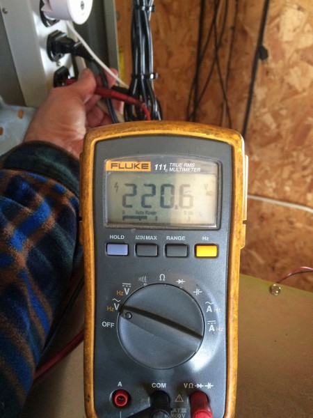
It seems the power company has some work to do. The other leg measures 28 volts to ground, which to me means the Neutral has been lost somewhere. Fortunately, the transmitter was running on 240, which looks normal on the voltmeter. Everything in the rack; the remote control, exciter, STL, etc have been damaged or destroyed.
Then, of course, there is this:
Utility line
That is the power and phone line in those trees, as it leaves the road and travels approximately 1,700 feet through the woods. It is a private line and the utility will not do any work until the trees are cleared away. In all fairness to the current owners, who have owned the station for not quite a year, this situation has been like this for a long time.
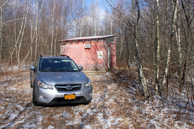
One of the reasons for the recent lack of posts; I have been busy rehabilitating several transmitter sites for various broadcasting companies. These are mostly FM transmitter sites and vary in power from one kilowatt to twenty-six kilowatts ERP. I enjoy project work, but I have been driving hither and yon, racking up 27,000 miles on my new car since last August.
Subaru Crosstrek XV at remote transmitter site, somewhere in rural New York
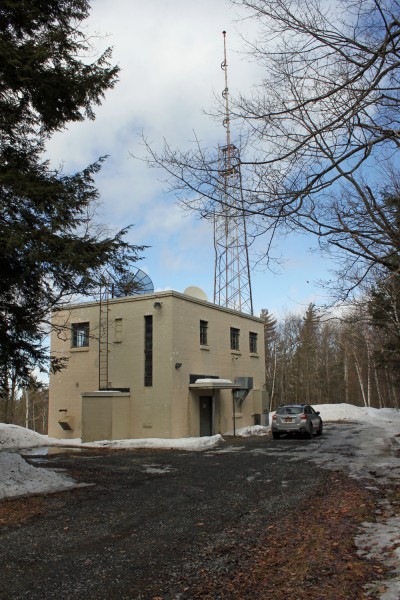
So, here is one transmitter site that I just finished; WFLY, Albany, New York. Removed Collins 831F2 transmitter which was functioning as a backup and installed new Broadcast Electronics FM20S. The Continental 816R2 is becoming a little bit long in the tooth for a main transmitter, being new in 1986. Thus, it was time to install a new unit, and I like the Broadcast Electronics solid state and tube designs. With the BE AM and FM solid-state units, their simplicity is their beauty. We service many BE transmitters, some are thirty years old and are still supported by the manufacturer.
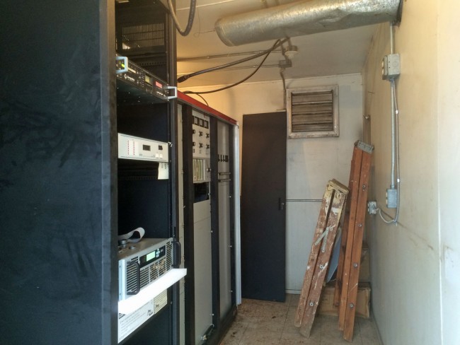
WFLY transmitter building, New Scotland, NY
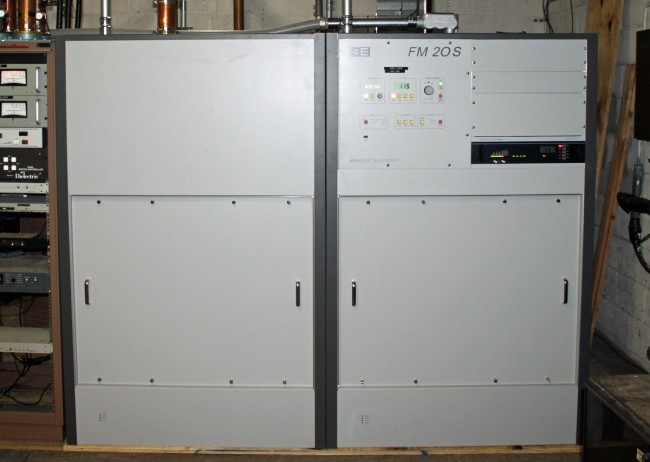
The BE FM20S transmitter is actually two FM10S cabinets combined with one controller. Each cabinet requires a 100 amp three-phase mains connection. This station’s TPO is 11.5 KW, so there is plenty of headroom in case the owners ever want to install HD Radio or replace the three-bay antenna with a two-bay unit.
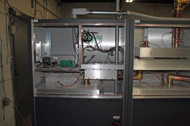
WFLY main transmitter, Broadcast Electronics FM20S
In transmitter cabinet two, above the exciter is room for HD equipment.
BE FM20S exciter housing
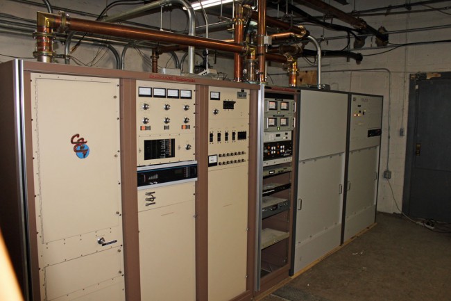
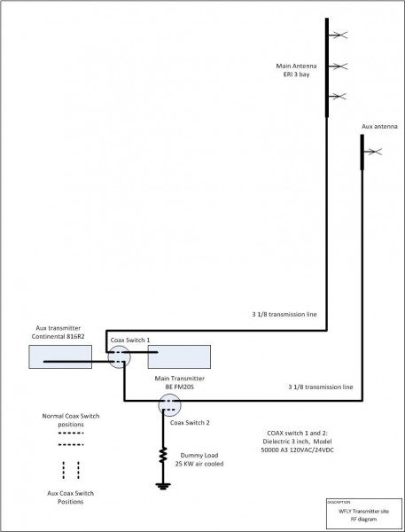
I also reworked the coax switches to provide an easier implementation of the backup transmitter. Basically, the main transmitter is on the main antenna, and the backup transmitter is on the backup antenna. We can move the second coax switch to test the backup into the dummy load. We can move the first coax switch to change antenna feeds.
WFLY backup and main transmitters
Pretty standard setup.
WFLY RF path diagram
We moved the Collins 831F2 from Albany to here to replace another, dead Collins unit at WKXZ in Norwich, New York. This transmitter is forty years old but still runs reliably. Of course, doing this work in the dead of winter added a degree of difficulty to the job, as the roads to both the WFLY and the WKXZ transmitter sites needed work to make them passable for a moving truck. In the end, we used a skid steer with forks on it to get the transmitter up the final hill and into the small WKXZ transmitter building.
I alluded to this in an earlier post: Open Delta three phase service. Some transmitter sites are fairly remote and three-phase power is not available. Occasionally, with lower-powered radio stations, this is acceptable because those transmitters can be configured to run on single-phase power. However, almost any transmitter above five kilowatts or so will require three-phase power. This is the case at the WQBJ transmitter site in Palatine Bridge, NY. The site is located in the middle of farmland and only has single-phase service. The nearest three-phase service is several miles away and the utility company wants several hundred thousand dollars to upgrade the line.
WQBJ transmitter site electrical service
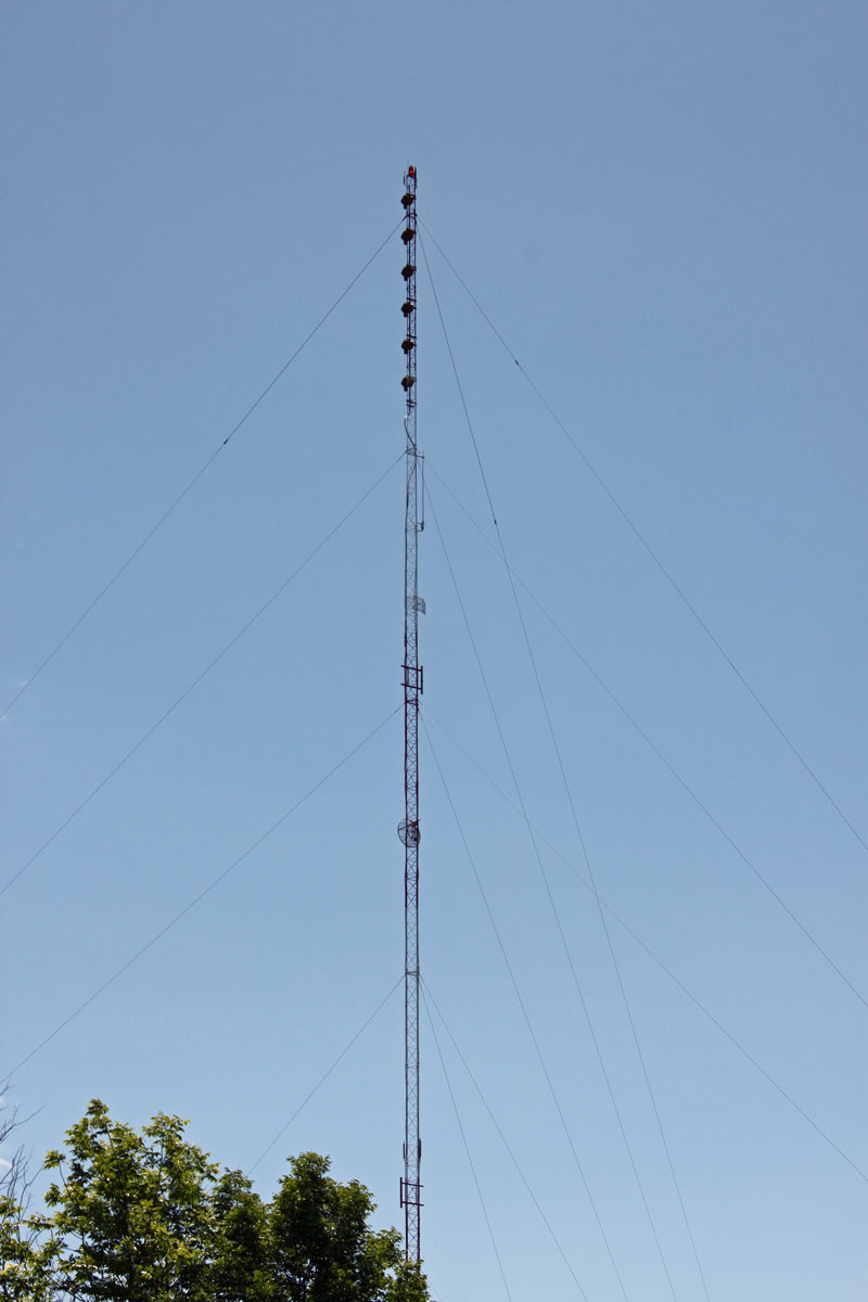
The station is a class B FM with a six-bay full wave-spaced antenna. Even so, the TPO is 17 KW, which makes some type of three-phase service a requirement.
WQBJ six-bay Shively 6810 antenna
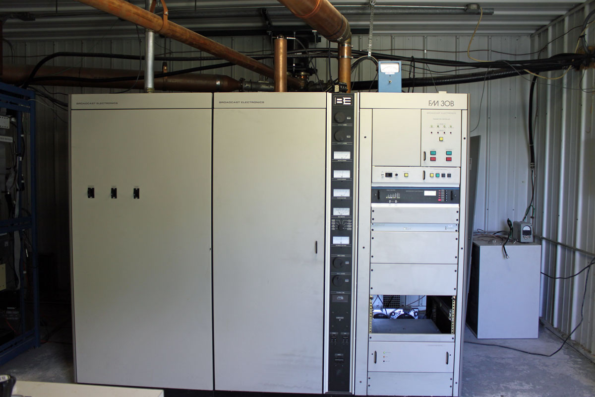
The main transmitter is a Broadcast Electronics FM30B, which is now 25 years old.
WQBJ main transmitter, Broadcast Electronics FM30B
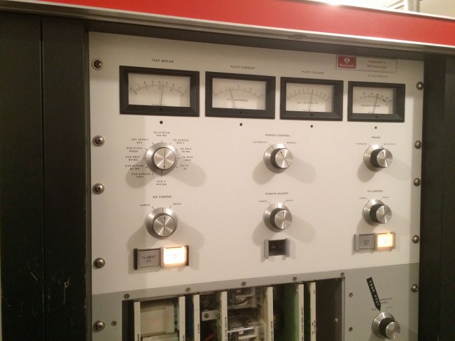
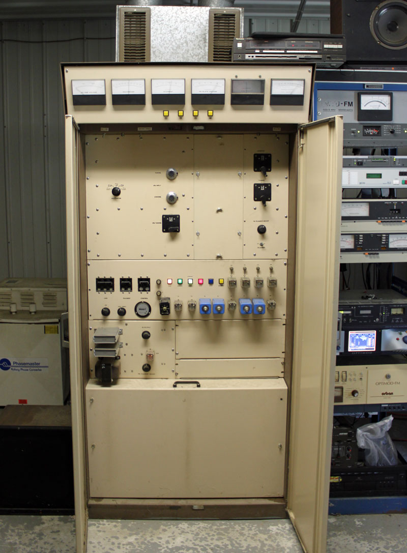
The backup transmitter is a CSI FM20T, which is almost forty years old.
WQBJ backup transmitter, CSI FM20T
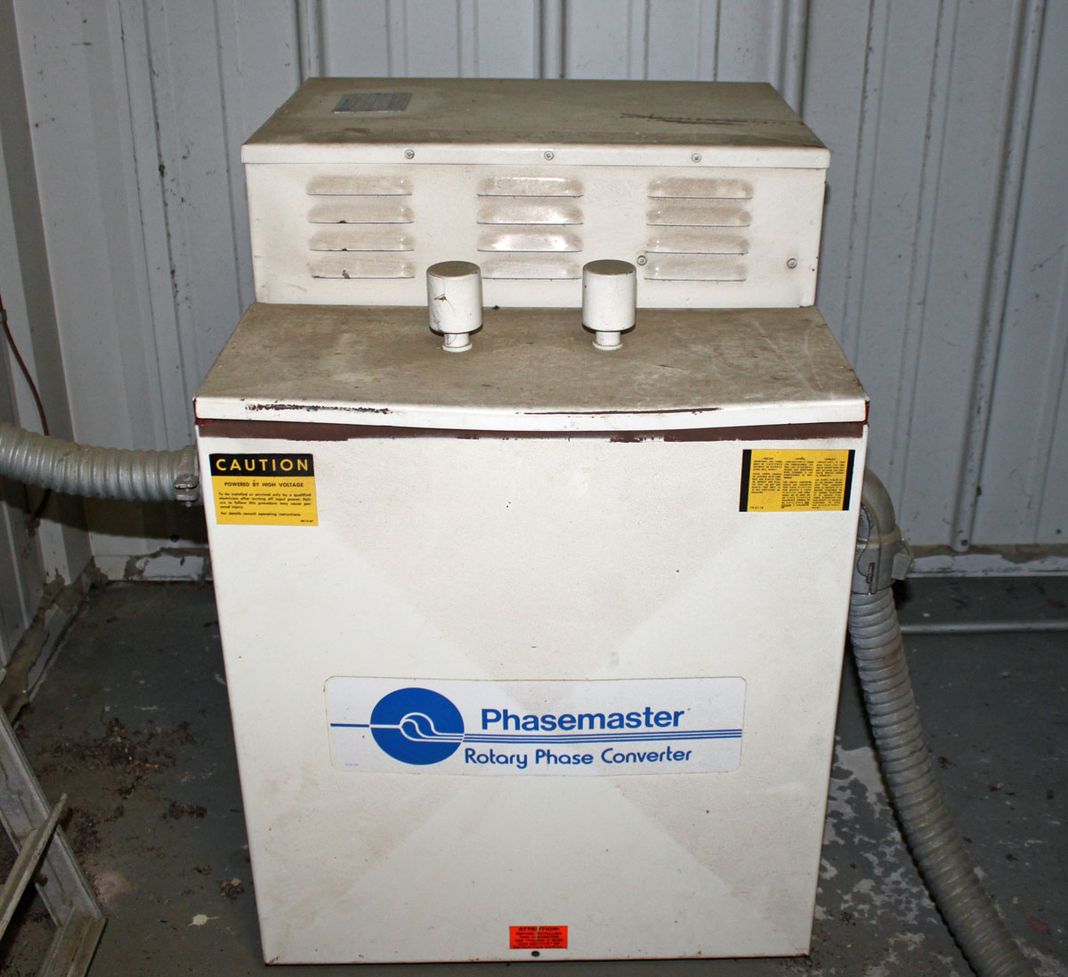
Rather than do an open delta service, which is not desirable for several reasons, both transmitters have their own rotary phase makers. From a reliability and redundancy standpoint, this is the right way to equip this site. The rotary phase makers are essentially a motor generator combination which takes the split phase power and generates a third phase.
WQBJ Phasemaster type T, backup three-phase converterPhasemaster parallel connection diagram
The phasemaster is is a 40 KVA unit and is connected to the backup CSI transmitter
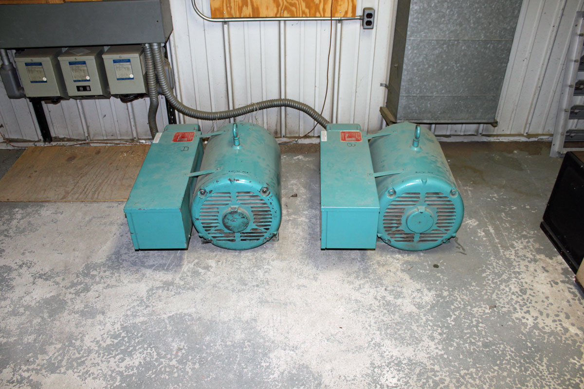
WQBJ ARCO Roto Phase, main three-phase rotary converter
The Roto Phase unit for the main transmitter is actually two 40 KVA units connected in parallel through dry core isolation transformers. Incidentally, the Roto Phase units need to have their bearings changed every ten years or so. This requires the units be disconnected, placed up on their end. To get the old bearing out, the housing has to be cooled with liquid CO2. Both units are due for new bearings soon, which should be a pleasant job indeed.
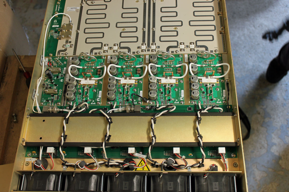
The newish Nautel VS2.5 transmitter installed at WJJR had an RF module failure. This particular model transmitter does not have slide-in RF modules as other Nautel transmitters do. To fix this transmitter, it has to be pulled out of the rack, flipped over, and opened from the bottom. The module replacement is very straightforward, there are five solder pads that connect to wires carrying the input, output, power supply, and bias voltages.
Nautel VS2.5 transmitter RF modules and combiner
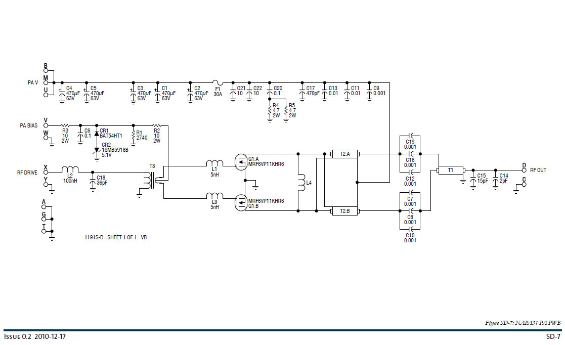
The troubleshooting guide gives good instructions on how to check the PA MOSFETS with a DVM. I found that 1/2 of the device in PA1 was bad:
Schematic Diagram, NAPA31
All in all, not a very hard repair. This was under warranty, so a replacement RF pallet was sent to the station without charge. The problem is more about where the transmitter is located:
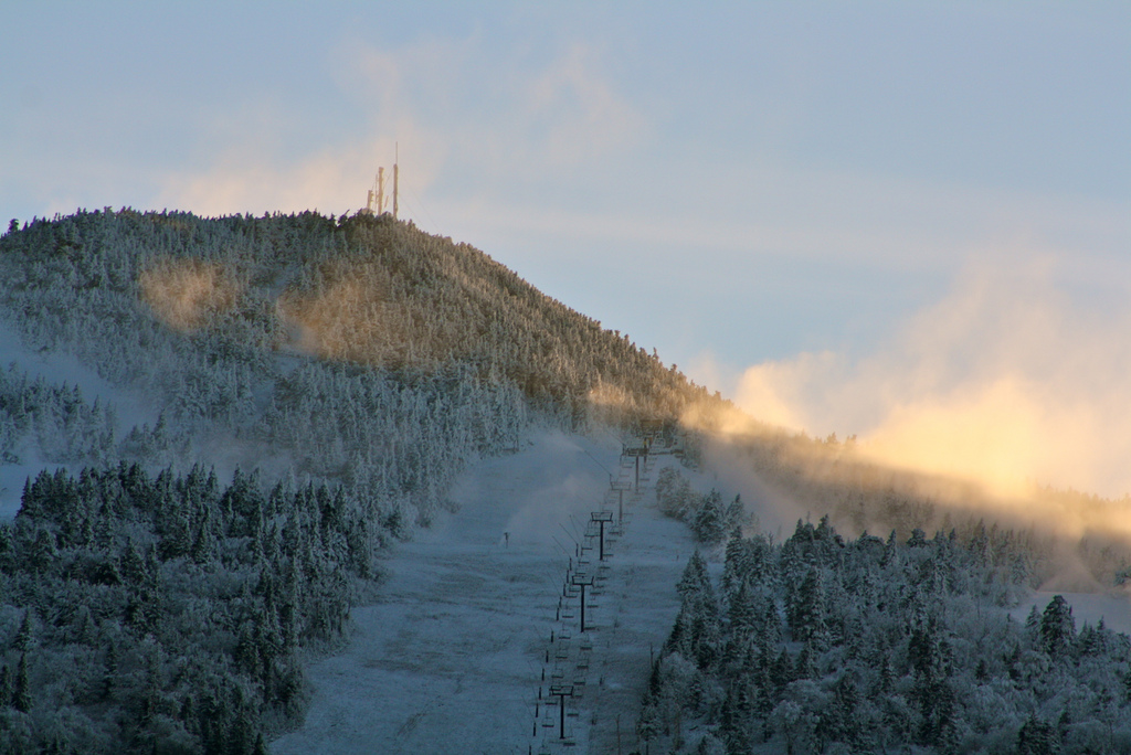
Killington Mountain, Killington, VT
Killington Peak is the second tallest mountain in Vermont, topping out at 4,235 feet (1,291 meters). In the winter, one can take the chair lift to the top. In the summer, the road is drivable with a four-wheel drive. In those in between months, access to the top can be very tricky at best. We had a pretty wet spring this year, so the roads up the mountain are just now becoming passable for vehicles.
Even after reaching the parking lot, there is still a 10 minute walk to the peak, another 200 or so feet up a steep, rocky trail.
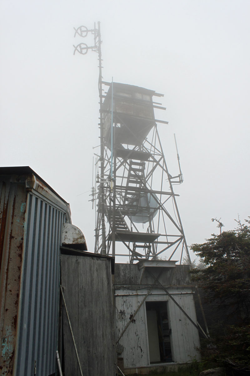
Further complicating things, this transmitter is wedged into this little shack, which holds; a BE FM3.5A transmitter (defunct WJJR), a Harris HT3 transmitter (WZRT), an ERI combiner, two racks of equipment (STLs, Exciters, remote controls, etc) a backup QEI transmitter, an Onan generator transfer switch:
Killington Peak fire tower, WJJR WZRT transmitter building
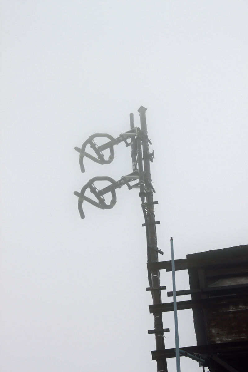
Both stations run into this ERI half-wave spaced antenna:
WJJR WZRT ERI antenna
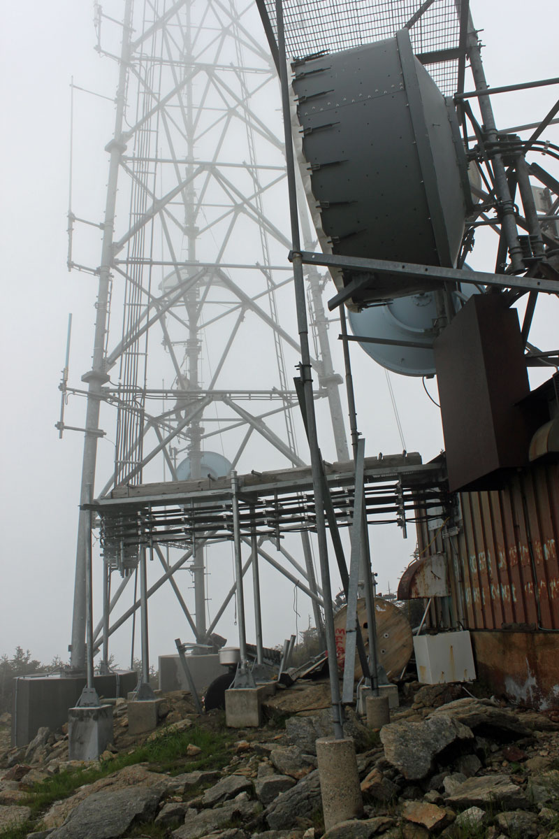
It is very tight in this transmitter room. There is a new tower on Killington Peak, which is still under construction. At some point, the plan is to move into the larger building next to the new tower.
Killington Peak tower
On a clear day, the view from the top is spectacular. On this day, the peak was in the clouds, so not so much:
Killington Peak view
It is a great site, the HAAT is 2590 feet (790 meters) and the stations carry forever on relatively low power outputs.