Hurricane season is here. This time of year makes me fondly remember hurricanes of the past and the things we had to do to get stations back on the air; walking a mile down a sandy spit of land, wading through swamp water to get to the transmitter shack, being threatened with arrest by the Connecticut National Guard, blow drying RF modules with a hair dryer, sleeping in a camper for a week… Ahhhh, good times, great times!
The one thing that I did learn if the disaster is big enough, expect none of the normal services to be functioning. That includes things like gas stations, fuel delivery, grocery stores, restaurants, hotels, UPS, roads, bridges, telephone service, internet service, etc.
It is not a far-fetched scenario for the main FM transmitter site to be out of commission and will not be available or accessible for some prolonged period of time. There might also be mitigating circumstances such as catastrophic tower failure, destruction of the transmitter building, flooding, or other major infrastructure disruptions. In those situations, calling the broadcast supply vendor of choice for a replacement might not be an option.
It has happened before…
All of these things got me thinking about how to fabricate a reliable FM broadcast antenna from simple materials available on hand. The FCC allows for temporary operation with an emergency antenna in part 73.1680, which reads:
(a) An emergency antenna is one that is erected for temporary use after the authorized main and auxiliary antennas are damaged and cannot be used.
(b) Prior authority from the FCC is not required by licensees and permittees to erect and commence operations using an emergency antenna to restore program service to the public. However, an informal letter request to continue operation with the emergency antenna must be made within 24 hours to the FCC in Washington, DC, Attention: Audio Division (radio) or Video Division (television), Media Bureau, within 24 hours after commencement of its use. The request is to include a description of the damage to the authorized antenna, a description of the emergency antenna, and the station operating power with the emergency antenna.
(1) AM stations. AM stations may use a horizontal or vertical wire or a nondirectional vertical element of a directional antenna as an emergency antenna. AM stations using an emergency nondirectional antenna or a horizontal or vertical wire pursuant to this section, in lieu or authorized directional facilities, shall operate with power reduced to 25% or less of the nominal licensed power, or, a higher power, not exceeding licensed power, while insuring that the radiated filed strength does not exceed that authorized in any given azimuth for the corresponding hours of directional operation.
(2) FM, TV and Class A TV stations. FM, TV and Class A TV stations may erect any suitable radiator, or use operable sections of the authorized antenna(s) as an emergency antenna.
(c) The FCC may prescribe the output power, radiation limits, or other operating conditions when using an emergency antenna, and emergency antenna authorizations may be modified or terminated in the event harmful interference is caused to other stations or services by the use of an emergency antenna.
In this situation, making a circularly polarized antenna would be overly complicated, so either a horizontally or vertically polarized antenna would be the most likely scenario. There are a few antenna types that readily lend themselves to field expedient fabrication.
These are, in no particular order:
- 1/2 wave wire dipole
- 1/2 wave tubing dipole
- 1/2 wave folded dipole
- 1/4 wave vertical ground plane
- 3/4 wave J-pole (end fed 1/2 wave antenna with 1/4 wave tuning stub)
Of these, the 1/2 wave wire dipole is the easiest to construct. Cut two wires, length (in feet) determined by the formula 234/Frequency (Mhz). Attach one wire to the center conductor and one to the shield, stretch to the wires out and tune for minimum SWR by cutting or adding small lengths to the ends. The total length for such an antenna would be approximately five feet and it could be mounted horizontally or vertically. The issue with a wire dipole would be bandwidth and power handling capability.
A 1/2 wave dipole made from tubing would have better bandwidth and power handling, but tubing is a little harder to work with when it comes to tuning the antenna.
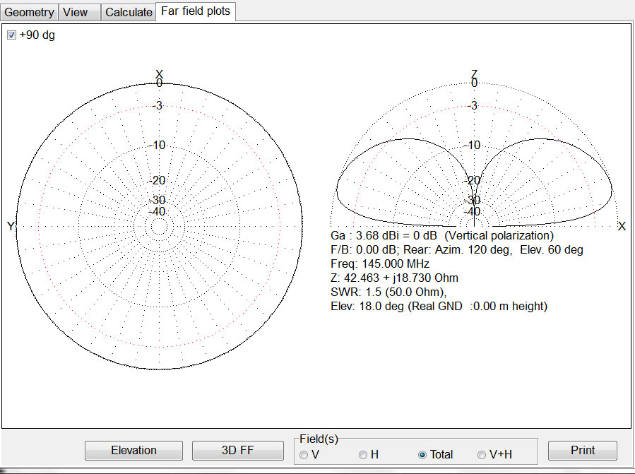
Frankly, if one is going to go through the trouble of using tubing to create an emergency antenna, the J-Pole (end-fed antenna with a 1/4 wave matching section) is probably the best. This antenna is easier to tune, does not need to work against a ground plane, and has good bandwidth and a low take-off angle, meaning more power is radiated out toward the horizon, giving it a good deal of gain over both a ground plane and dipole antenna. Additionally, when using standard RG-8, RG-214, LMR-400 or another similar transmission line, a well-matched antenna might be able to accept about 1 KW of input power, which would net approximately 4.4 KW ERP. Not an insignificant sum, especially in an emergency situation.

There are many J-Pole antenna calculators available online, but many of them include a 20-inch or so section of tubing below the tuning stub that can be electrically coupled to the supporting structure. This configuration defeats the main advantage of the antenna, creating a good deal of upward radiation. It is a better idea to use a non-conductive support piece and keep any conductive materials at least 1/2 wavelength or greater from the radiating portion of the antenna.
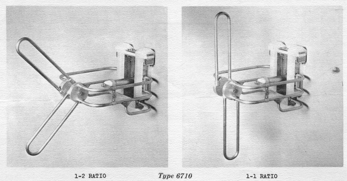
The basic j-pole antenna looks like this:
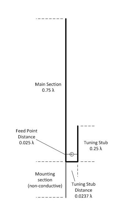
The radiating part of the antenna starts above the tuning stub. Basically, the 1/4 wave stub is shorted at the bottom, the feed point is adjusted away from the shorted end until a 50-ohm impedance point is found. The center conductor of the coax is attached to the 3/4 wavelength section, while the shield is connected to the stub. The critical distances are the tuning stub length and the distance of the feed point from the shorting section. I created an excel spreadsheet (.xls) that can be used to create all the lengths required to fabricate one of these antennas. That spreadsheet can be had here: J Pole Calculator
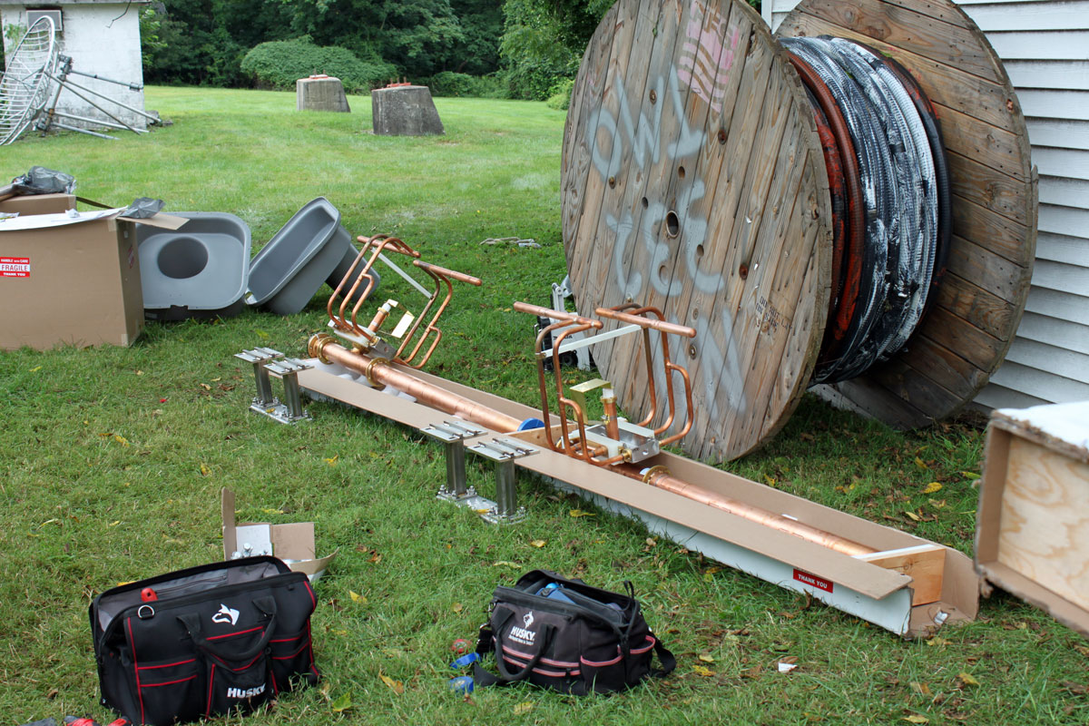
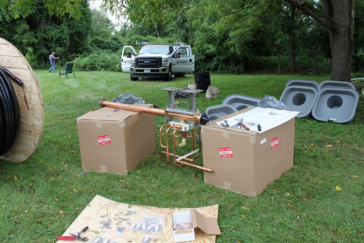
Having a few moments of time to spare, I thought it would be fun to build one of these and put the analyzer to it. I think testing things in the real world is a good exercise and I always enjoy working with antennas anyway. Looking in the basement, I found some 3/4 inch copper tubing, a tee, an elbow, and a few end caps. The complete list of parts is thus:
| Part | Amount | Use |
| ¾ copper tubing | 78-96 inches (196-244 cm) (frequency dependent) | Main section |
| ¾ copper tubing | 26-32 inches (66-82 cm) (frequency dependent) | Tuning stub |
| ¾ copper tubing | 2.5-3 inches (6.35-7.62 cm) (frequency dependent) | Tuning stub short |
| ¾ copper tubing | 2 inches (5.08 cm) | Mounting section, bottom of T to MIP threaded adaptor |
| ¾ copper T section | 1 each | T section for joining main section to tuning stub |
| ¾ copper 90 elbow | 1 each | Elbow |
| ¾ copper end cap | 2 each | End cap on tubing |
| ¾ to 1 inch copper MIP threaded adaptor | 1 each | Antenna Mounting |
| 1 inch PVC FPT threaded adaptor | 1 each | Insulating mounting connection |
| 1 inch PVC | Approximately 20-25 inches (50-65 cm) | Insulating mounting material |
| 1 inch stainless steel hose clamps | 2 each | Attaching the coax to the antenna feed point |
| RG-8, RG-214, LMR-400 or other transmission line | As needed, including 5-6 turns, six inches in diameter to form RF choke at feed point | RF choke needed to keep RF off of coax shield |
One important detail to remember when using the above spreadsheet, the measurements are to the closest side and not the center. Thus, if something measures 2.5 inches, it is metal to metal. Some basic soldering skills are required, but assembly is relatively straightforward. In a pinch, almost any conductive material could be used including aluminum, brass, steel, EMT, rigid conduit, or even iron pipe.

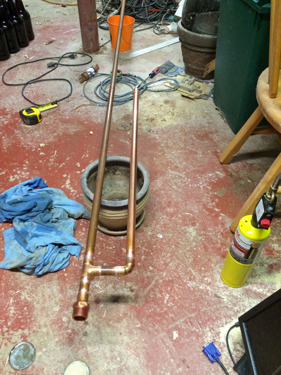
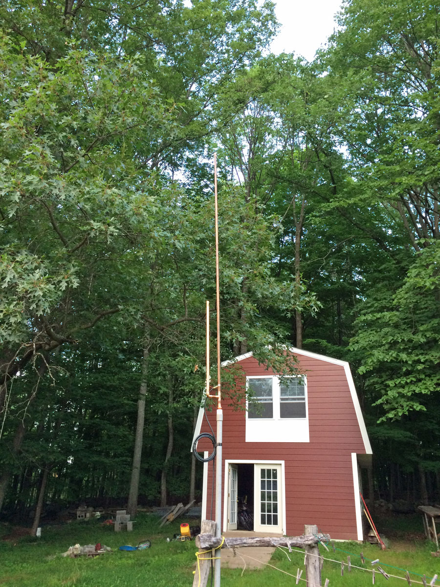
I made this particular J-pole antenna on 87.9 MHz because I didn’t feel like chopping up all my 3/4-inch tubing. Cutting and soldering the tubing took about half an hour. Designing and fabricating the feed point system for another half an hour. I’ll throw another hour in for rounding up the parts, tools, etc. Thus, the entire antenna was constructed in about two hours. I used my AIM 4170D to find the proper feed point. If I were going to actually use this antenna, it would then be a matter of finding a mounting location and running the transmission line.
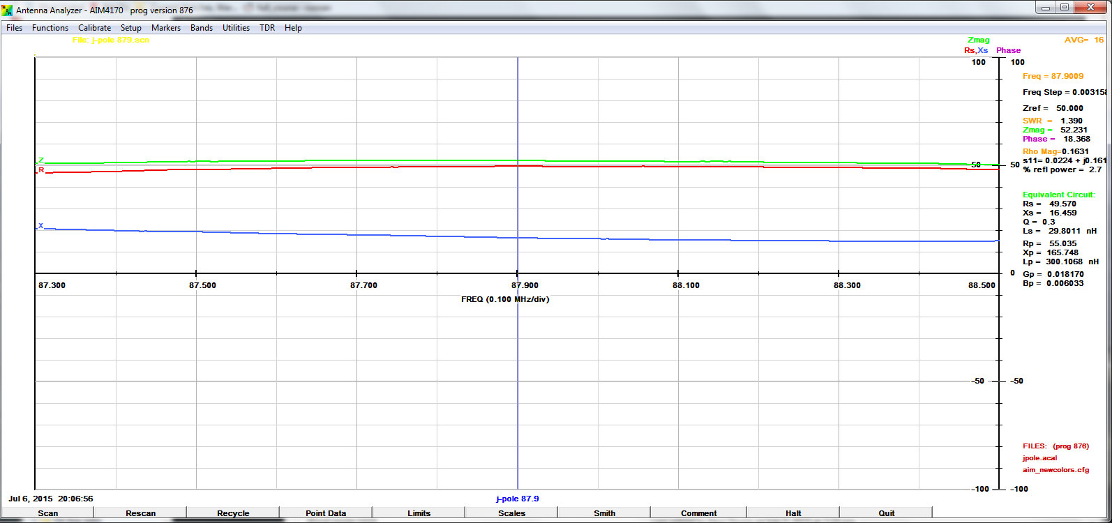
Actually, I was less than happy with this. While the antenna is nice and broad across several channels, there are 16 ohms of inductive reactance that is impossible to get rid of. That gives an SWR of 1.4:1, which is not great. With that kind of load, I would be reluctant to run more than a couple of hundred watts into this antenna. The interesting thing is, that graph is the first one, with everything set as calculated in the spreadsheet. After that, I could make the impedance and reactance worse, but not better.
Still, in a pinch, I would use this antenna until something better could be found.
Update:
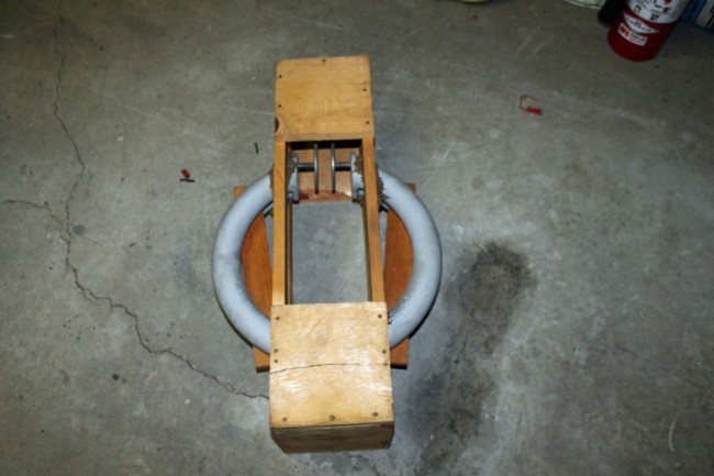
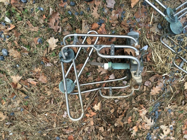
As promised, a picture of the feed point:
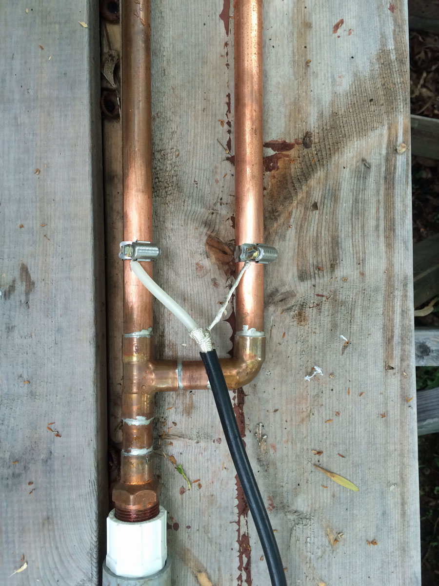
The hose clamps are not optimum, I am sure a better way to attach the feed line to the antenna can be fabricated, but again, I was thinking of an emergency situation and the parts which may be available from local sources.