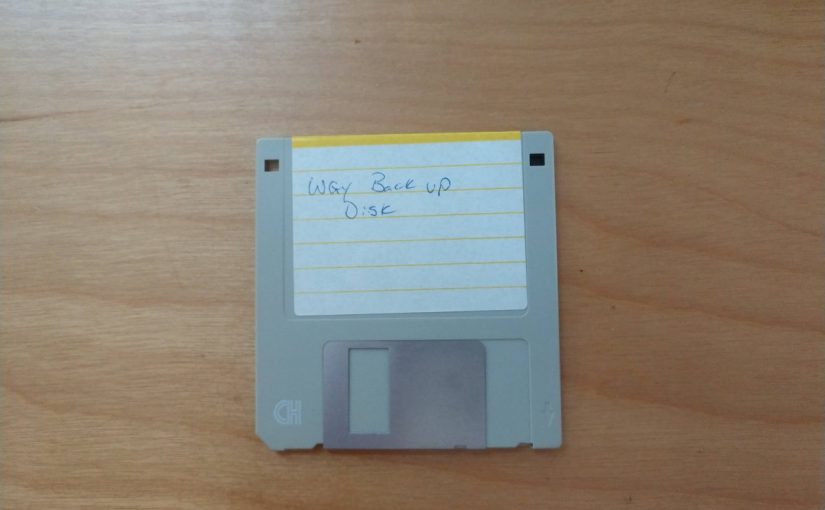
While cleaning out a closet at home, I found a 3.5-inch disk with some interesting memos. When I left WGY in the spring of 1996, I made a backup copy of all the items in my documents folder. I figure it was an intelligent thing to do since I was still working for the same company in the role of Director of Engineering.
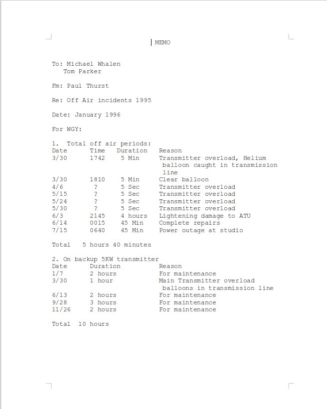
In those days, management wanted a precise accounting of all off-the-air incidents. The studio was staffed with a board operator who monitored the air signal at all times. Anytime the carrier dropped, there would be a note in the transmitter log. Those 5 second interruptions are likely due to thunderstorms. Lightning would strike somewhere nearby inducing an EMP on the tower. The venerable MW-50B would kill the PDM for a brief period as protection from VSWR. If I were at the transmitter site, the insulators in the guy wires would start crackling anytime a storm was within 10 miles of the site.
The helium balloon incident involved one of those metallic helium party balloons which escaped and ended up tangled in the 240-ohm open wire transmission line. This caused multiple VSWR trips for both the main and backup transmitters. I remember pulling up to the site and having a bit of a chuckle. By the time I got there, the balloon had mostly been burned into oblivion by the RF and the station was back on the air.
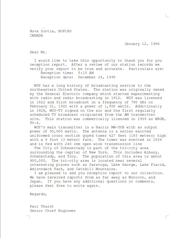
Another interesting item is our standard reception report form letter:
WGY reception report letter; name and address redacted because of the internet
These were printed out on WGY letterhead and mailed. I sent out several of them every week. I think the furthest away was Cape Town, South Africa.
The model for Radio Engineering these days is such that one engineer is covering multiple stations in various locations. At the very least, this person has a full (if not overflowing) plate. Thus, when something breaks, the procedure very often is; to pull the suspected module or board, call the manufacturer and order a replacement. That works as long as the manufacturer supports the model in question or has parts. As we all have learned by now, replacement parts are subject to the global supply chain, which is tenuous.
Then there is the question of AM transmitters. Is it worth it to replace an AM transmitter these days? I suggest it would depend on the market and revenue. In some cases, yes. In other cases, keeping the older equipment running makes more sense.
Troubleshooting is becoming a bit of a lost art. In addition to the time it takes, we tend to be unfocused and obsessed with rapid gratification, ready for the next social media post. What is lacking is the ability to take apart the layers of a problem, accept our initial analysis may be flawed, move beyond those assumptions, and work until the issue is solved. Troubleshooting is often like a crime scene investigation. There are several logical steps;
Assess the current situation; take steps to ensure it is safe to proceed. Remove all power from the transmitter and don’t work on failed transmission equipment during thunderstorms
Gather evidence; look for fault indicators, alarms, automated log entries, burned components, abnormal meter readings, etc
Check external factors; power failures, lightning or storm damage, excessive heat, moisture, etc
Check internal factors; aged components, bad cables or connectors, improperly seated boards or components, and obvious signs of damage
Work from one side of the issue to the other
Check the maintenance logs (if there are any) to see if this problem has occurred before and what was the fix
Use available resources; troubleshooting guides provided in equipment manuals, factory support, and available test equipment
If a failed component is found, make sure that it is the problem and not a symptom of something else
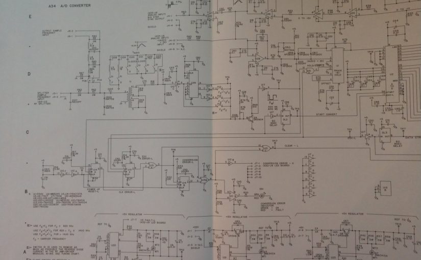
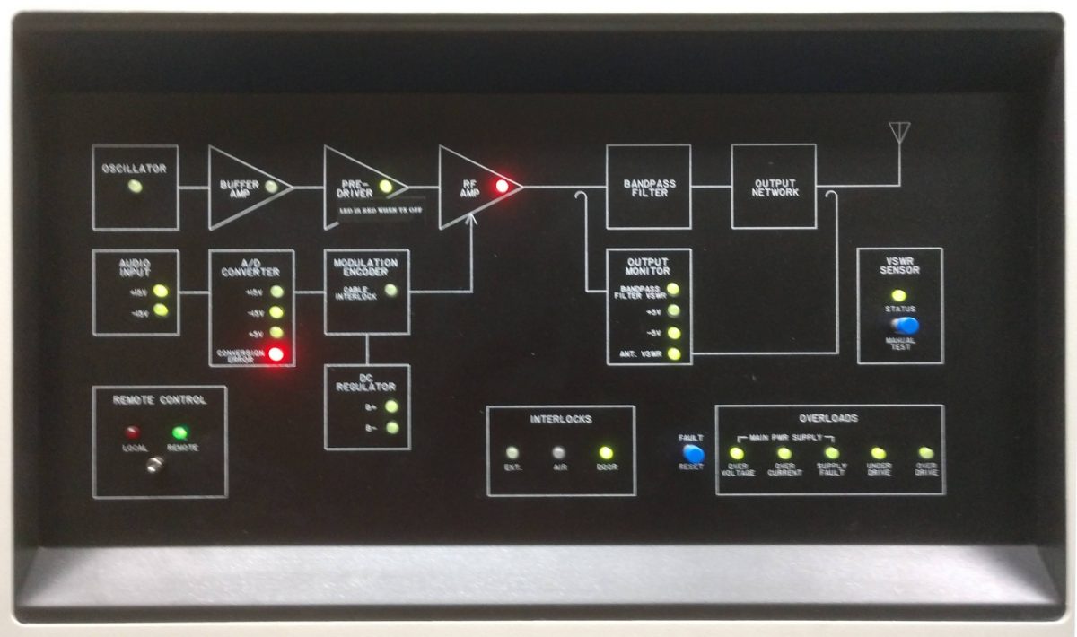
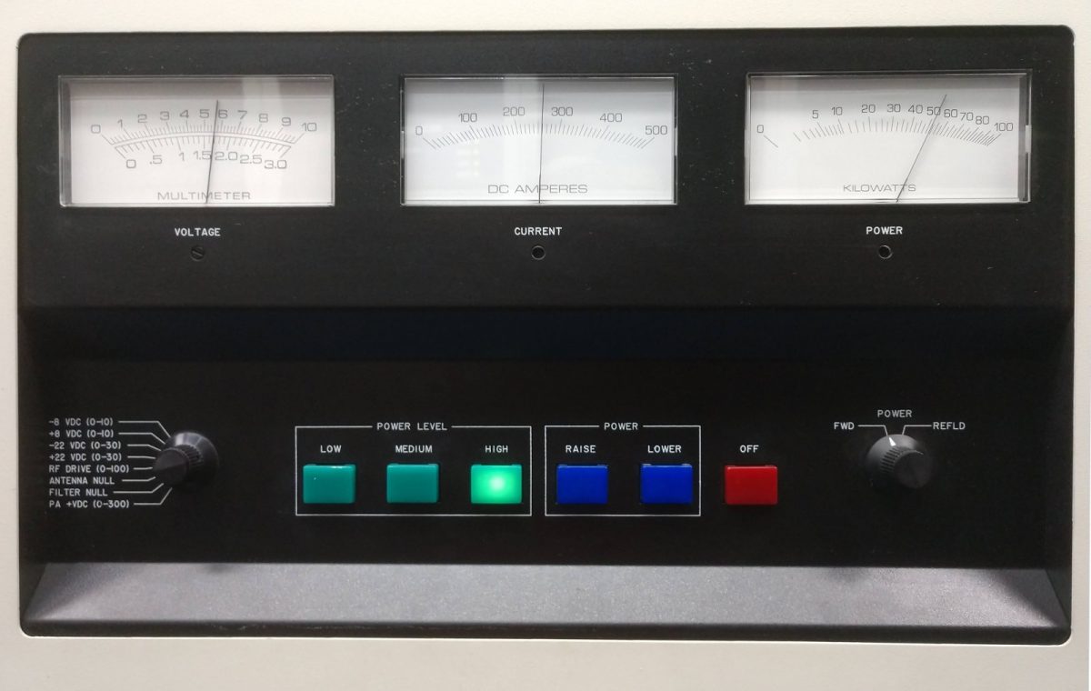
Here is a good example of a recent troubleshooting evolution; I went to change over to transmitter #2 and these fault lights appeared:
DX-50 transmitter, faulted, no power output
The conversion error on the A/D converter indicates why the transmitter power output is zero.
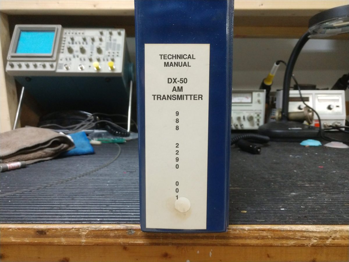
The first step; secure the transmitter, remove all power, etc. Next, consult the book!
The Harris DX-50 manual gives good troubleshooting guidance. This transmitter was manufactured on March 22, 1990. It has been a reliable unit, to date. Section K.4 Analog to Digital Converter (A34) of the manual suggests loss of audio clock frequency sample due to the following;
Loose connection with the carrier frequency sample cable coming from the RF drive splitter (A15)
Bad or missing jumper connections on P-10, frequency divider section
Bad U-29 (74HC161, 4-bit binary counter, only in use if the carrier frequency is above 820 KHz, Not Applicable)
Bad U-12 (74HC14, Schmitt trigger)
Bad CR13 or 14 (1N914)
Fortunately, there was a working DX-50 about 15 feet away, so I was able to make some measurements at various places on the A/D converter board.
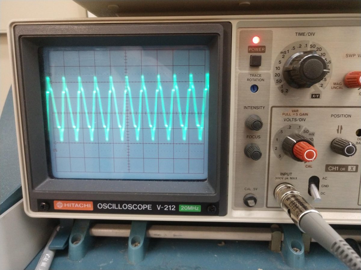
On the working transmitter (DX-50-1), at the RF sample input (input of R83) on the A/D converter board, I see a nice strong sine wave, on frequency:
Carrier from RF drive splitter to A/D converter boardCarrier frequency
Second, I measured the logic pulses on TP-6, as described in the manual. Those look good.
On the non-working transmitter, I made the same measurements and found a fuzzy sine wave way off frequency on the input of R83. The logic pulses on TP-6 was normal.
Definitely lost the RF sample. Since the transmitter is 32 years old, I suspected the cable (#92, RG-188 coax) between the RF drive splitter and the A/D converter had gone bad. Perhaps rubbed through on a rough metal edge or something like that. Several checks with a Fluke DVM showed that there were no shorts to ground or internal conductor shorts. End-to-end checks on both the shield and inner conductor proved good. So, not the cable…
I then went on a bit of a wild goose chase suspecting the output from the oscillator to be low or the drive regulator power supply was defective. The drive level going into the PA was close to normal but slightly lower than the previous maintenance log entry. Also, drivers 8A and 8B were both on, which is not normal and made me suspect the drive regulator.
I made a call to GatesAir and spoke with a factory rep, who had me swap out the A/D converter, oscillator, driver power supply regulator board, and the buffer amp/pre-driver module between the working and non-working transmitter (while the low-power aux was on the air). With the working transmitter close by, I was able to confirm that these boards or modules were not the cause.
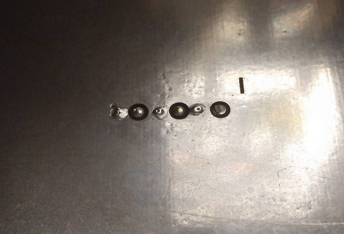
Finally, I went back to the RF drive splitter and use my camera to take a picture:
DX-50 RF drive splitter (A15) J-17, board side
There is a 6-pin connector on the underside of the board (J-17). Pin 2 (from the right) is the center conductor and pin 1 is the shield of the cable going to the A/D converter board. Upon closer examination, the solder joint on pin 2 is suspect. I re-heated this connection with a soldering iron and viola, the transmitter started working again.
DX-50, returned to service
The extenuating circumstances; the air conditioning at this site was slowly failing and that part of the transmitter was subjected to heat cycling several times. More recently the HVAC system was in the process of being replaced, of course, on one of the hottest days of the year. This pulled a lot of warm, humid air into the room. Also, as this is transmitter #2, it was not in regular use until recently (we began a procedure for operating on alternating transmitters for two-week periods).
All of this work took place over the course of two and a half days or so. That would be a lot of time for the module swap guys who tend to move on to the next outage quickly. On the other hand, buying a new 50 KW AM transmitter is an expensive proposition these days and there are very long lead times on some of these units. Being persistent and focused paid off in the end.
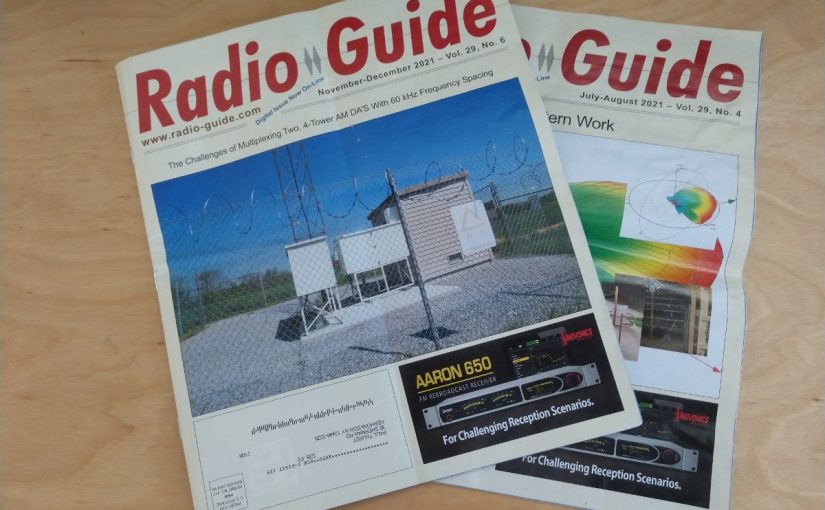
As some of you may have noticed, recently I have been writing some articles for Radio Guide. There are several good reasons for this, but the most important one is education. I believe that terrestrial radio will be around for a few more years. As others have noted, there are fewer and fewer broadcast engineers. Those that understand high-power RF and all its intricacies are fewer still. It is important that a cadre of knowledgeable broadcast engineers carry on.
The internet is a great thing. However, it depends on cables of some type to exist. As we know, cables can be damaged. In addition to cables, there are routers, core switches, servers, and so on. All of that equipment can fail for various reasons. People have been working hard to improve the resiliency of the internet. That is a good cause, to be sure. However small it may be, there is still a chance that the internet can fail. Worse still, this can happen during some type of natural disaster or other emergency. Thus, during such an emergency, Radio can and will function as a vital information source provided that the station is on the air and has a program feed. That is also a good reason to keep the current RF STL paths in place as much as possible.
The Radio Guide articles are a great way to pass along some of that hard-earned experience to others. I also want to put supplemental information here for those interested to download. Things like charts, forms, pictures, videos, etc.
What I am planning on is to list the articles here, then put links to any supplemental information provided below that subheading.
We were doing some overnight maintenance on one of the class A AMs in New York the other night. The aged Automatic Transfer Switch on the electrical service entrance needed to be replaced, thus the power to the entire facility needed to be cut while the old switch was removed and the new switch installed.
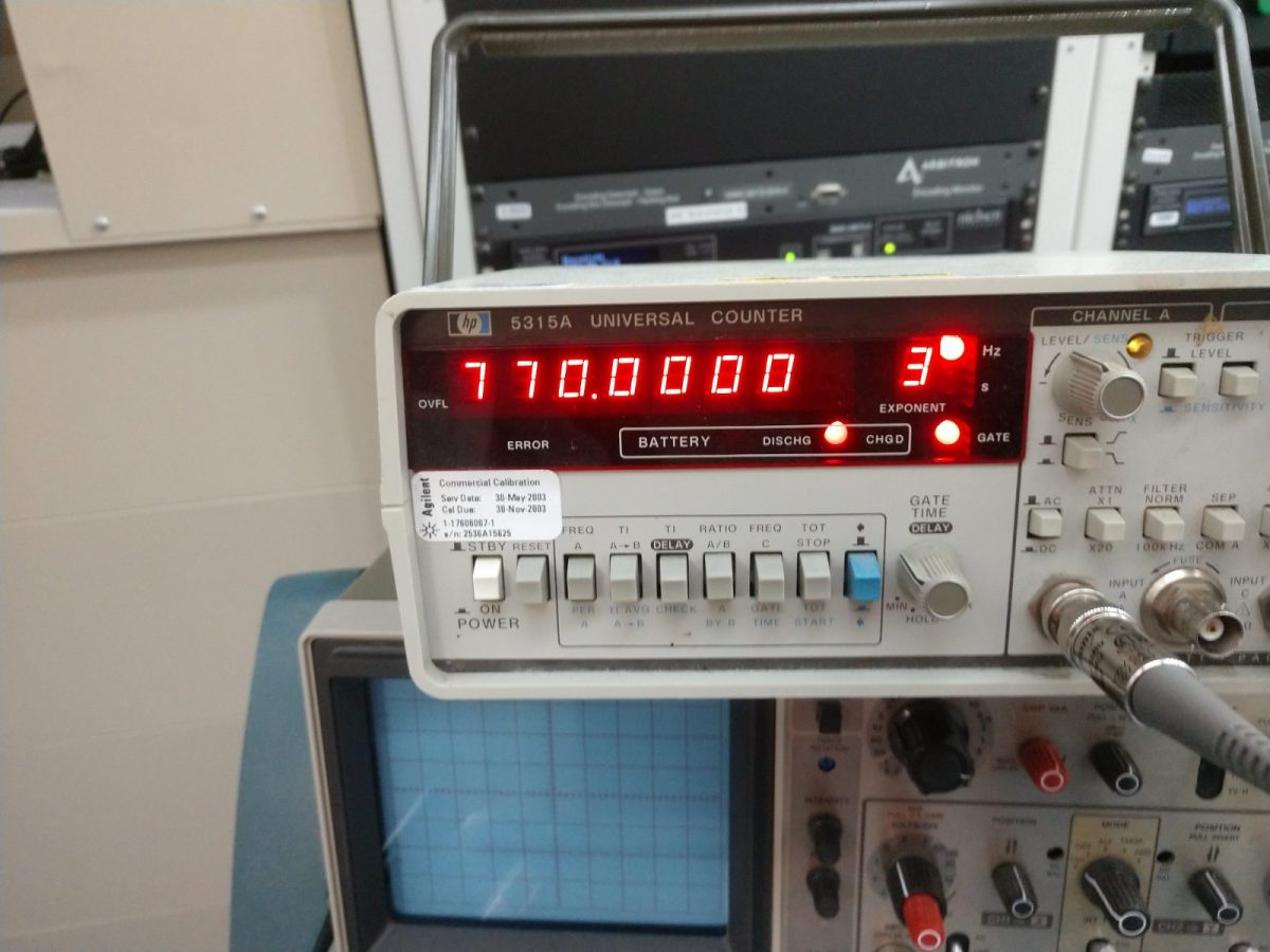
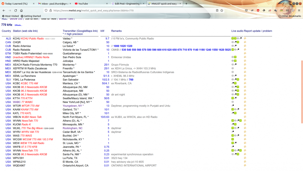
During this period, we took the opportunity to do some maintenance on the main and aux towers. All went well. We also notified the National Radio Club that the station was going to be off the air so that their members could log some rare DX. My thought process here was that we might also find a few daytimers who were still on the air or a DA night who was operating with their daytime facilities. A quick look at MW list shows that there are several such stations on 770 KHz:
MW list, North American 770 KHz
Alas, the answer was no, nobody was on the air who should not have been. Reports from Cape Cod, Massachusetts; New Foundland, Canada; Manassas, Virginia; West Union, South Carolina; and southwest, Ohio have Cuban and South American stations on the air (Radio Artemisa, Radio Rebelde, Radio Oriental) but all of the east coast daytimers are off.
The 180-degree main mast for WABC is in good shape. You can deride AM and say it is outdated. However, it still gets out and covers vast distances.