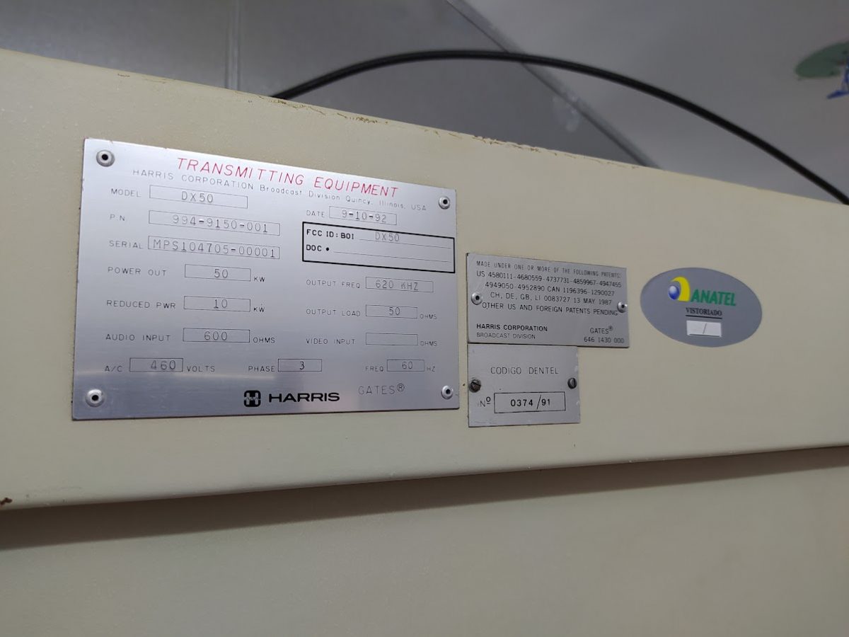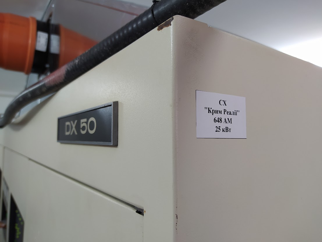
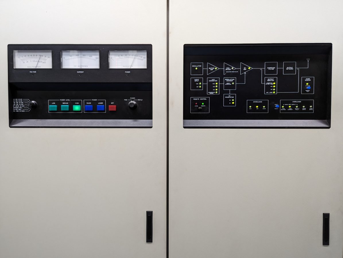
This lovely transmitter is 33 years old! I thought we’d celebrate by changing the electrolytic capacitors! It appears that some of the capacitors were changed in 2009, but many are original to the transmitter. Gates Air recommends replacing the electrolytic capacitors during the course of regular maintenance cycles. Dried-out capacitors can lead to a variety of mysterious fault conditions including low drive levels, poor audio quality, difficulty starting the transmitter, and so on. See Harris service bulletin AM-579-JK.
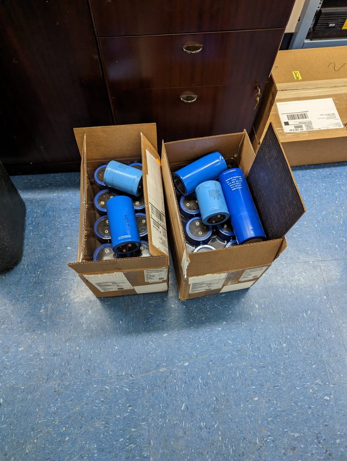
Some of the Low Voltage Power Supply capacitors were at least partly dried out. They felt a little bit light and one of them rattled when I shook it.
Gates Air has a full replacement kit, part number 973-2100-391. When I looked into it, the price of this kit is very reasonable and is closely aligned with the prices from Mouser Electronics.
Here is a full list of capacitors needed, I put the Mouser part numbers in just in case:
| Nomenclature | Amount | Gates Air PN | Mouser PN |
| Cap, 5,100 uf 350 V | 17 | 524-0341-000 | 598-DCM512T350DG2A |
| Cap, 5,500 uf 200 V | 4 | 524-0219-000 | 75-36D552F200DF2A |
| Cap, 15,000 uf 100 v | 2 | 524-0322-000 | 594-MAL210119153E3 |
| Cap, 76,000 uf 40 v | 4 | 524-0342-000 | 75-36DX763G040DF2A |
| Cap, 120,000 uf 40 V* | 2 | 524-0380-000 | 75-36DX124G040DJ2A |
*See Harris service bulletin AM-474-TLH for information on the -8 volt power supply.
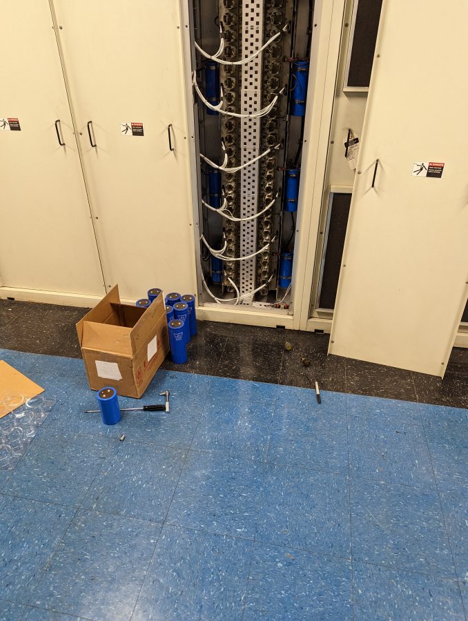
Most of the capacitors in the PA section were original to the transmitter, as well as those in the 30-volt and 60-volt driver supply.
One important detail; pay attention when installing these things. You do not want to reverse the polarity on an electrolytic capacitor, it will likely explode. These units are pretty big and the explosion would be loud and messy.
With that done, I also went through the transmitter and reset all of the voltage levels according to the factory test data sheet. When it was returned to the air, it sounded great!