AM Radio Improvement Plan

There has been lots of hand wringing and ink spilled regarding the sorry state of affairs in the senior service. AM is plagued with problems; interference, poor bandwidth, etc. To that end, the NAB has launched studies and initiatives and hired all sorts of pricey consultants to consult with. Here is my own AM improvement plan and it is rather simple:

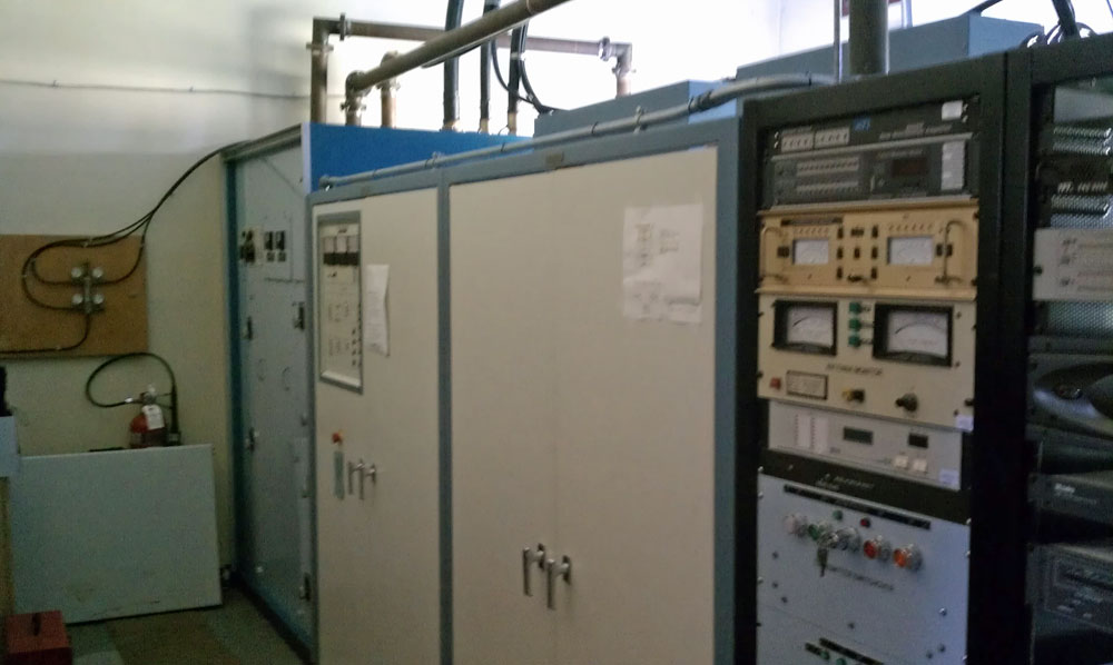
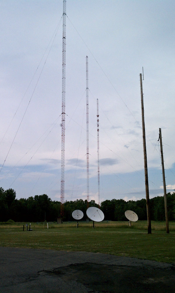
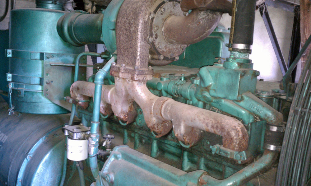
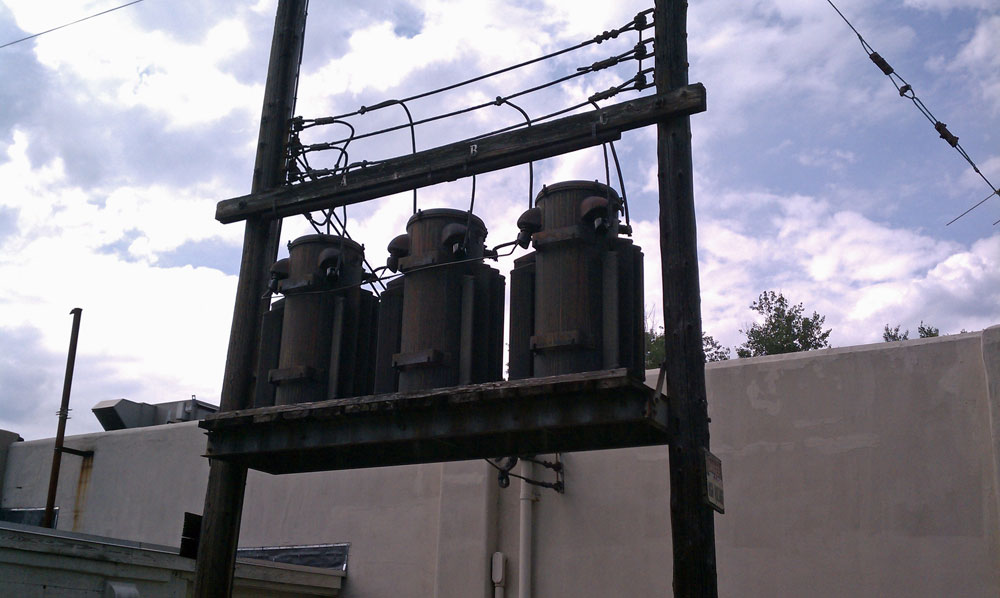
  1. Clean up the transmitter site.
  2. Get rid of AM HD radio.
  3. Variable IF bandwidth receivers.
  4. Improve Programming.

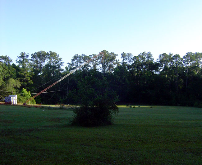
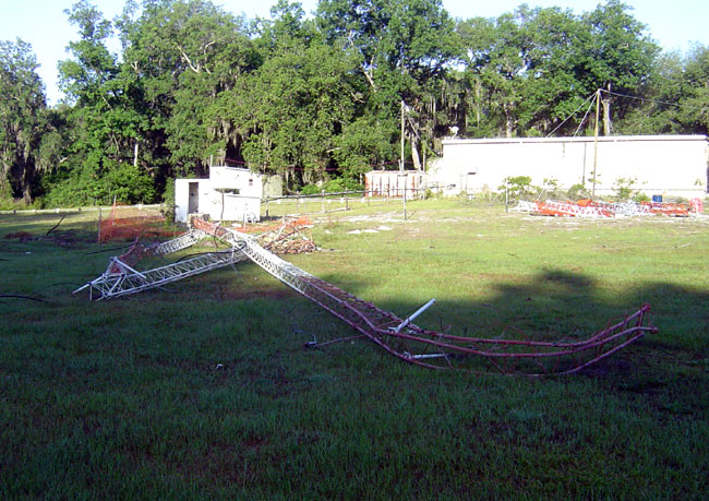
How many of us have seen AM transmitter site dumps? Deferred maintenance, malfunctioning directional arrays, trees growing up on the ground system, flooded buildings and ATU’s,  rusty towers, transmitters not a full power, ground system deteriorated or missing all together, just to list a few problems.  Many AM transmitter sites are technical disasters.  Think that these things have no bearing on the AM station’s signal?  Think again.

differed maintenance, AM transmitter site
Differed maintenance, AM transmitter site (there is a tower in there somewhere)

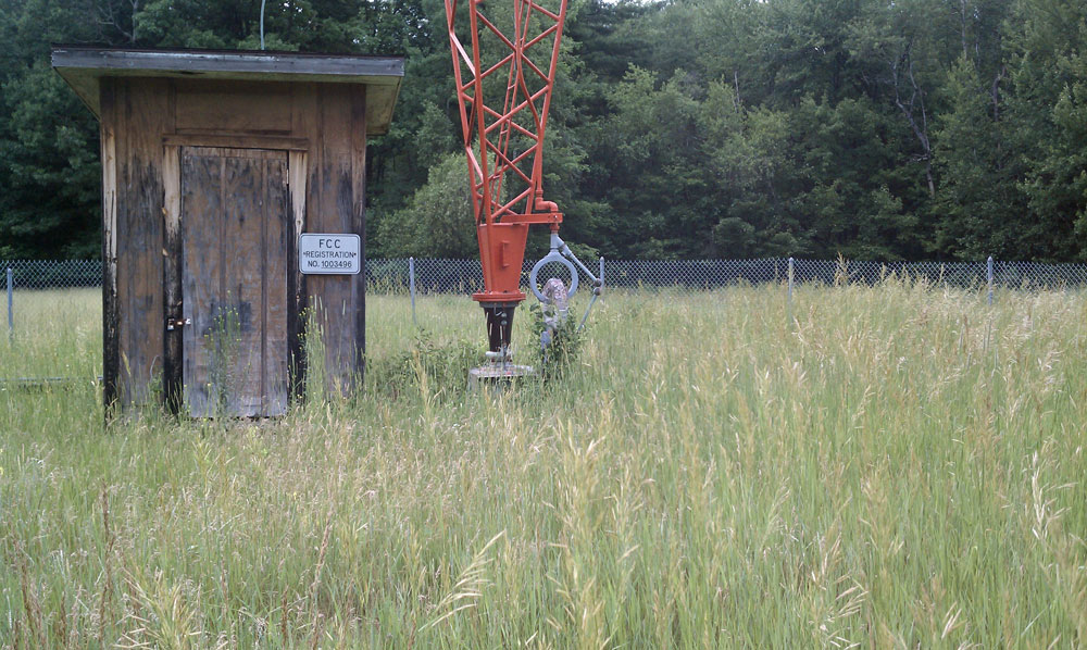
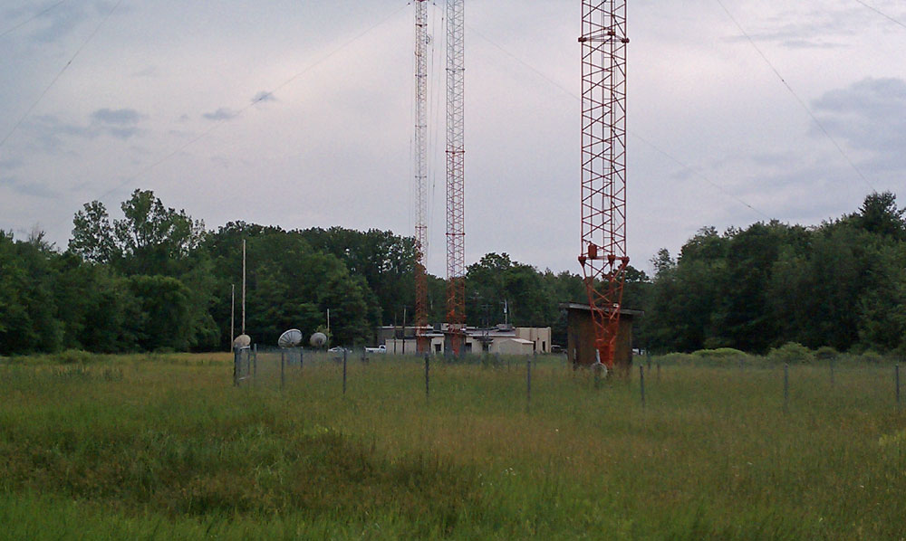
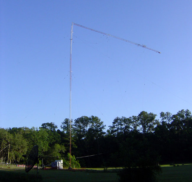
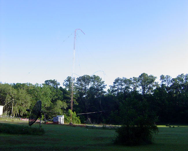
Trees growing around the tower base can attenuate the signal by 30%.  A comment from a well known engineering firm:

…Recently XXX field engineers had occasion to measure an AM station at XXXX kHz before and after removing vegetation in the vicinity. The station had a quarter-wave tower. The base area had grown up in brush and hardwood trees to a height of perhaps 30 feet (9m) and this extended from near the base across the entire ground system. After clearing (cutting, no ground system disturbance), the signal measured at some 16 locations on four radials went up a uniform amount of about 15% or 1.2 DB. That’s about a 30% increase in radiated power…

That is an inexpensive power boost and they didn’t even have to file with the FCC! A 1 – 2 dB power gain is pretty nice and can mean the difference between a listenable signal and static.  How many times have I heard the lament that AM band is full of noise and not listenable.  Certainly, there are major challenges in the urban listening environment.  Putting forth a better signal will overcome some of this electrical noise.

There is a reason why engineering standards were developed for the physical plant; they work.

There is no cure for the noise that AM HD Radio puts out into the adjacent channels.  This self interference benefits none, not even the station transmitting AM HD Radio.  This dubious technology has proved itself a non-starter and should be discontinued.  For smaller station owners, the cost of implementing AM HD Radio is prohibitive.  Licensing of a proprietary modulation scheme, new transmitting equipment, specialized exciters plus any needed bandwidth improvements to AM antenna arrays can easily exceed $100,000.00.  Unfortunately, it is often the small AM radio operators that are making a good showing, and serving their community of license and making money.  These are the very stations that are hurt the most by adjacent channel AM HD Radio interference.

Receiver design over the last twenty to thirty years has been the greater issue with perceived low AM broadcast quality.  AM receivers have an average bandwidth of just 3-4 KHz, which is slightly better than telephone quality.  AM broadcasting has gotten a bad wrap because of this and there are many comments about how AM is “inferior quality” to FM.  With a quality older receiver, AM can sound very good.  Of course, the receiver manufactures all point adjacent channel interference as their rational for reducing IF bandwidth.  Why not leave it in the hands of the user? The GE Superradio had this feature with a “wide” and “narrow” setting for AM reception.  They worked remarkably well.   A receiver could also be designed to automatically increase IF bandwidth at higher received signal strengths.

Finally, as the saying goes; Garbage in, Garbage out (GIGO).  This holds true for many things including radio programming.  Expecting that mediocre satellite syndicated news talk will garner great ratings and huge revenues is silly.  For years and years, station owners have put minimal effort into AM radio and expected big returns.  It is not working.  AM stations that go against that trend; those with unique formats (Gasp! Music, on AM?), local content, and community oriented programming can and do succeed.  They are fighting an up hill battle in both directions.  With all of the business pressures from larger broadcast groups, interference issues and negative viewpoint on the viability of the AM band, one wonders how long they can last.

Hums no more

My first job as Chief Engineer was at WPTR and WFLY in 1991. I was young and it was a learning experience. The WPTR transmitter was a Harris MW50A, which reliably went off the air every six months. The transmission lines going out to the towers had fallen off of their wooden support posts, trees were growing up in the antenna field, and sample lines were going bad. In short, it was a mess.  Even so, the station was well-known and well-liked in the community. One could still see echoes of greatness that once was.

When Crawford Broadcasting purchased the station in 1996, they put much money and effort into renovating the facility.  Replacing the Harris transmitter with a solid state Nautel, replacing the phasor and transmission lines, cutting the trees from the field, painting the towers, renovating the old transmitter building into a new studio facility, and finally removing the old Butler building that formerly housed the “Gold Studios.”

Then the depression of 2008-20?? hit.  Once again, the place has fallen on hard times.  WDCD-AM has been silent since last April.  The cost of running the 50 KW AM transmitter being too much to bear in the current economy.  Formatically, the station drifted around for several years.  According to the STA to go silent:

WDCD WILL SUSPEND OPERATIONS FOR A PERIOD DURING WHICH IT WILL DEVELOP AND PREPARE TO DEPLOY A NEW PROGRAM FORMAT AND REPOSITION ITS VOICE AND IDENTITY IN THE COMMUNITY.

They may need to do something slightly non-religious to survive.

While we were waiting for the utility company to turn the electricity back on after yesterday’s fire, I took a short walk around the WDCD-AM site and took some pictures.  The transmitter disconnect thrown,  fuses are pulled,  it is kind of sad to see the Nautel XL-60 dark:

Nautel XL-60 AM transmitter.  WDCD Albany, NY
Nautel XL-60 AM transmitter. WDCD Albany, NY

I apologize greatly for the blurry picture, it was taken with my cellphone camera, my good camera being back at home on my desk.  Radio stations, when they are on the air, seem like they are alive.  Machinery hums, fans move air, meters move, and there is a sense of purpose.  Silent radio stations give me a sense of foreboding like something is terribly wrong.

WDCD three tower array, Albany, NY

View of the towers without Butler Building.  The towers are 340 feet tall, which is 206 electrical degrees on 1540 KHz.  The site was constructed like this to suppress skywave signals toward ZNS, Nassau, Bahamas.  ZNS is the only clear channel station allotted to the Bahamas by NARBA.  The other station WDCD is protecting is KXEL, Waterloo, IA.  During the 90’s, I received many QSL requests from Norway/Finland and even a few from South Africa.  I know that the station had a large following in most of New England.

WDCD tower base, tower three
WDCD tower base, tower one (furthest from building)

Tower one tower base.  This IDECO tower had to have the top 60 feet replaced after it was hit by an airplane in 1953.  The tower base also had to be replaced in the late 1980’s as it was crumbling and falling apart.  To do this, Northeast Towers used railroad jacks and jacked the entire tower up off of the base insulator.  They re-formed and poured a new base, carefully letting the tower back down on a new base insulator about a week later.

WDCD towers looking back toward the transmitter building

Antenna field looking back at the transmitter building.  If you work at radio transmitter sites, I encourage you to take pictures of all these things, as someday, they will all be gone.

WDCD bomb shelter
WDCD bomb shelter

The “bomb shelter” and 220 KW backup generator,  constructed by FEMA in 1968 as part of the BSEPP.  This used to have an emergency studio and enough diesel fuel for fourteen days of operation.  Now, the bomb shelter has a kitchen and bathrooms.  The underground storage tank no longer meets EPA standards and has been pumped out.

WDCD Onan generator
WDCD Onan generator

The Onan generator is conservatively rated at 220 KW, surge rating 275 KW.  These things were way over-constructed, so it is likely it would easily run 225 KW all day.  It has an inline six-cylinder engine with a massive flywheel.  When the engine is stopped, it takes about twenty seconds for the generator to stop turning.

Three phase service
Three phase service

National Grid, 3 pot, 480 volt, 3 phase service, original to the 1947 building.

I wonder if it will return.

Backup cooling

One of the issues that I have seen at many transmitter sites is inadequate cooling. Time was, when mostly tube transmitters were in use, a simple fan connected to a thermostat was all that was used to cool most transmitter sites.  Even then, however, that setup was lacking for several reasons.

Those reasons are:

  • The amount of cooling provided was limited by the amount of heat in the outside air.  On cool winter days, this is not a problem, but on hot, sticky summer days it could be.
  • No removal of humidity from the transmitter room was possible.  This often leads to excess oxidation, corrosion of metal parts, and so on.
  • No matter how much filtering was used, bugs, dirt, and other debris were sucked into the fan, making transmitter room cleaning a chore.

With solid-state transmitters, air conditioning is required.  Solid-state transmitter devices are far less rugged than tubes when it comes to heat.  In a high-heat situation,  a tube transmitter will keep running until its control circuits malfunction, or it catches on fire.  A solid-state transmitter will crash long before either of those things happen.

Air conditioners should be adequately sized for the heat load plus a little extra.  That information can be found in a previous post: A tale of two air conditioners.

As we all know, equipment malfunctions.  When an air conditioning system goes bad at a transmitter site, things start to happen fast if there is no backup.  That is when a backup cooling fan can save the day.  A good rule of thumb for sizing a cooling fan is to exchange the total volume of the transmitter room every two minutes accounting for resistance from louvers and intake openings.

3200 CFM cooling fan, WHUD transmitter site

This fan is connected to a 120-volt contact on a thermostat attached to the ceiling of the transmitter room.  The thermostat is set to 90 degrees, which gives a good bit of headroom for the air conditioners to maintain the room temperature while turning the fan on before the room gets too hot. It is also important to monitor the room temperature via remote control.  Having an alarm contact connected to the fan thermostat is also a good idea.

There is no such thing as too much backup.  Installing a louvered cooling fan affords a little bit of extra insurance.

Tower take down pictures

A few years ago, I was involved in removing and rebuilding an AM radio station tower in Gainesville, Florida.  The old tower was a hollow leg tower that was rusting from the inside out.  It was installed around 1960 or so, but the actual records were sketchy, as the original studio building burned down in 1984.  In 2005, the tower climbers came out to relamp it and refused to climb it because one of the legs was rusted through.  Therefore, a replacement tower was ordered and delivered.

Prior to starting work, a temporary wire antenna was constructed.  Since there were two radio stations diplexed to this tower, it became a bit of a chore to get both signals (980 and 1430 kHz) tuned into the same temporary antenna.  In the end, the components available could not create a good load for the 1430 station, so a separate temporary wire antenna was erected for that station.  Both stations ran at 1 KW into their respective antennas until the new tower was finished.

WDVH, 980 Gainesville, FL.  Top of tower coming down
WDVH, 980 Gainesville, FL. Top of tower coming down

Top section of a 240-foot guyed tower on its way to the ground. This tower had an inner and outer set of guy anchor points. The top section came down after the last guy wire on the outer anchor was cut.

Remains of WDVH tower

Truncated tower.

Last section of WDVH tower falling

Bottom section of tower on its way to the ground.

Old WDVH tower on the ground

Tower on the ground. In keeping with the theories on tower failures, this tower fell within about 1/3 its height.  The wire antenna supports and the new tower sections can be seen in the background.  It took the tower company about a week to stack the new tower.  This was done in July, therefore the average daytime temperature was about 100° F  (37° C) with frequent afternoon thunderstorms.