A few years ago, I was involved in removing and rebuilding an AM radio station tower in Gainesville, Florida. The old tower was a hollow leg tower that was rusting from the inside out. It was installed around 1960 or so, but the actual records were sketchy, as the original studio building burned down in 1984. In 2005, the tower climbers came out to relamp it and refused to climb it because one of the legs was rusted through. Therefore, a replacement tower was ordered and delivered.
Prior to starting work, a temporary wire antenna was constructed. Since there were two radio stations diplexed to this tower, it became a bit of a chore to get both signals (980 and 1430 kHz) tuned into the same temporary antenna. In the end, the components available could not create a good load for the 1430 station, so a separate temporary wire antenna was erected for that station. Both stations ran at 1 KW into their respective antennas until the new tower was finished.
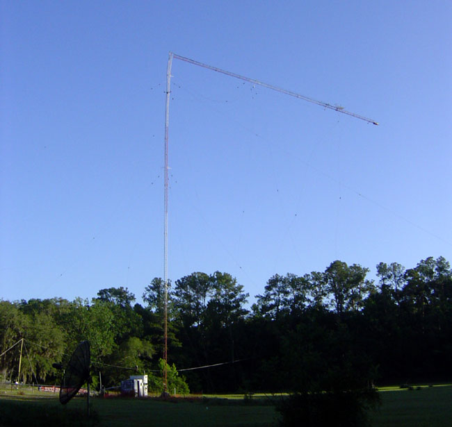
Top section of a 240-foot guyed tower on its way to the ground. This tower had an inner and outer set of guy anchor points. The top section came down after the last guy wire on the outer anchor was cut.
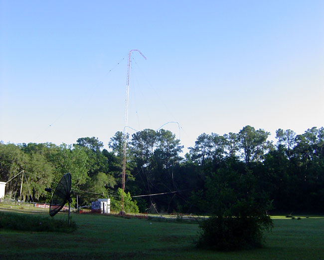
Truncated tower.
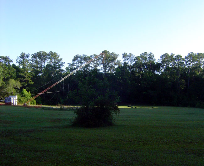
Bottom section of tower on its way to the ground.
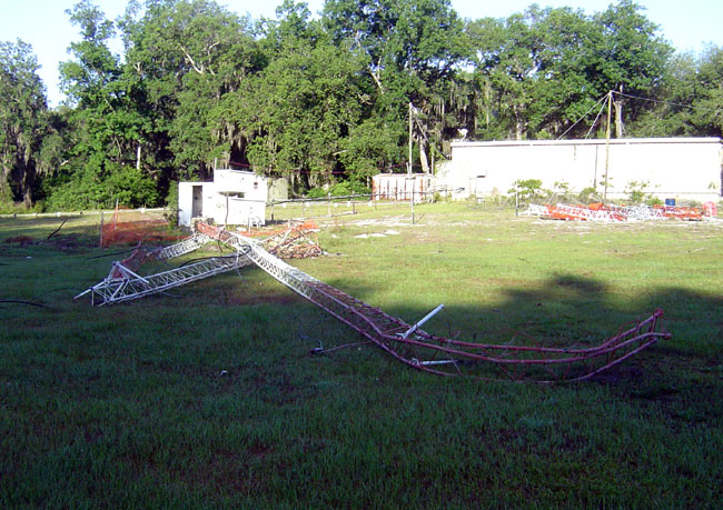
Tower on the ground. In keeping with the theories on tower failures, this tower fell within about 1/3 its height. The wire antenna supports and the new tower sections can be seen in the background. It took the tower company about a week to stack the new tower. This was done in July, therefore the average daytime temperature was about 100° F (37° C) with frequent afternoon thunderstorms.

On a very small scale, that sort of corrosion damage happens a lot here.
We are in what was (prior to digital TV) a fringe area for commercial stations in Adelaide, about 90nm as the crow flies from here. There was only one National (ABC – a bit like your PBS) and one local commercial station for many years. Prior to that there was only the ABC. So most homes (probably 2 out of 3) had a 30-60 foot steel tube triangular based tower bolted on concrete pads via a long j bolt embedded in six feet of concrete as anchors. These were very sturdy and I’ve never seen one pull out or snap at that point. However some are now fifty years old. The legs were hollow steel, galvanised and open at top and bottom. Where the pads are above ground, there has been no water accumulation and many old towers are still quite sound, even if they have surface rust. Others, well, little old ladies tend to build gardens and such and bury the footings. Water accumulates in the base of the legs and you get them eating away from the inside. One day when there is a decent windstorm, the tower falls over, takes out power lines, damages a roof or a car or a shed and requires cranes and cutting gear to remove. On average we get two collapses a season.
People are not cutting down towers or cutting them off at just above roof height as some still mount local antennas on them. We are all digital now, the analogue signal has been turned off so a single horizontally polarised UHF yagi is fine for all channels instead of the CA16 horizontal collinear for Adelaide tv, the 114 for Band 1 local tv (ch 1 and 4 – now defunct ch4 was in the middle of the fm radio band) and a uhf for the SBS (Special broadcasting service – foreign language etc) This could get interesting as it required a triplexer, padding of the signal from the local antenna and some tweaking to prevent odd effects from the strong local Ch4 signal affecting the weak Ch9 signal.
I have a suspicion that one of the local radio towers (around 90m) is getting a bit tired, what are the thoughts on replacing that with a Crossed Field antenna? I know they are somewhat controversial, but several independent tests do show they work, with an increase in the ground wave at the expense of low angle radiation. Not much good for HF but pretty much ideal for MF and LF broadcasting.
I know there are a few around now, Egypt, Italy, Brazil and a LF in the English Channel and they seem to work well and don’t require large expensive towers or extensive radial networks. I realise they are not the ‘traditional’ vertical radiating tower, but other than being a little tricky to set up and tune initially, I can’t seem to find a down side. Any comments?
Geoff
Geoff, I remember studying the cross field antennas in the late 90’s early 00’s. My conclusion then was there was not enough data, including side by side comparisons with 1/4 wave vertical radiators with full ground systems. Since then, several have been constructed and studies. I believe the best study I have read is the Silsden Cross Field Antenna report.
That confirms what you are saying about use for MF/LF. It seems that the original claims of a 1/10 wave length CFA being equal to a 1/4 wave tower were a little off. The Silsden CFA was 1/6 wave length and supported on a 5 meter tall platform, which seems to be a performance requirement. Also, I see the distribution of impedance and reactance is slightly irregular about the carrier frequency. I do not know if that can be corrected with a tuning network or not. It does look like an interesting design.