I am wondering what is going on with the HD Radio rollout these days. Particularly the all-digital AM conversion scheme being bantered about so often last spring. Not much is being discussed publicly about that or the AM revitalization. I have found FCC Commissioner Clyburn’s remarks at this week’s NAB Confab interesting. HD Radio is paid lip service here:
There are hurdles: if broadcasters do not broadly embrace the HD technology and the multicasting and other enhancements that it makes possible, listeners will have few incentives to buy digital receivers. Likewise, if no consumers own digital receivers, then there is no reason to broadcast in digital.
But I’m not worried. More than 15 million digital receivers have been sold so far, and that number will only rise. Thirty-three auto manufacturers include or plan to include digital receivers in their cars, and those receivers are standard equipment in over 80 models. This will dramatically increase the number of digital receivers in the coming years.
But in the solutions for AM broadcasters, HD Radio is not mentioned at all. What is put forward as a six (actually five) step plan to revitalize AM radio turns out to be some rearranging of the deck chairs and a little more. Cliff notes version for the FCC’s AM revitalization:
- Open a one-time filing window for AM license holders to acquire an FM translator
- Relaxing community coverage rules for AM licensing allows greater flexibility for transmitter siting
- Eliminating the “Ratchet Rule” used in nighttime allocation studies for new facilities
- Permitting more widespread use of MCDL technologies by eliminating STA requirements
- Reducing minimum field strength requirements by twenty-five percent allowing the use of shorter towers
While those options may save an AM license holder some money, none of them do anything to improve the technical quality of AM broadcasting. Several of them (#2, 4, and 5) will, in fact, if widely implemented, reduce signal levels over cities of license, making electrical noise and interference problems more prevalent. This is a step in the wrong direction.
These points are basically a rehash of some of the MMTC’s (Minority Media Telecommunication Council) ideas for a radio rescue first bantered about in 2009.
This demonstrates that the NAB and the FCC are not at all serious about revitalizing the AM band but merely marking time and making it look good until the final transmitter is switched off.
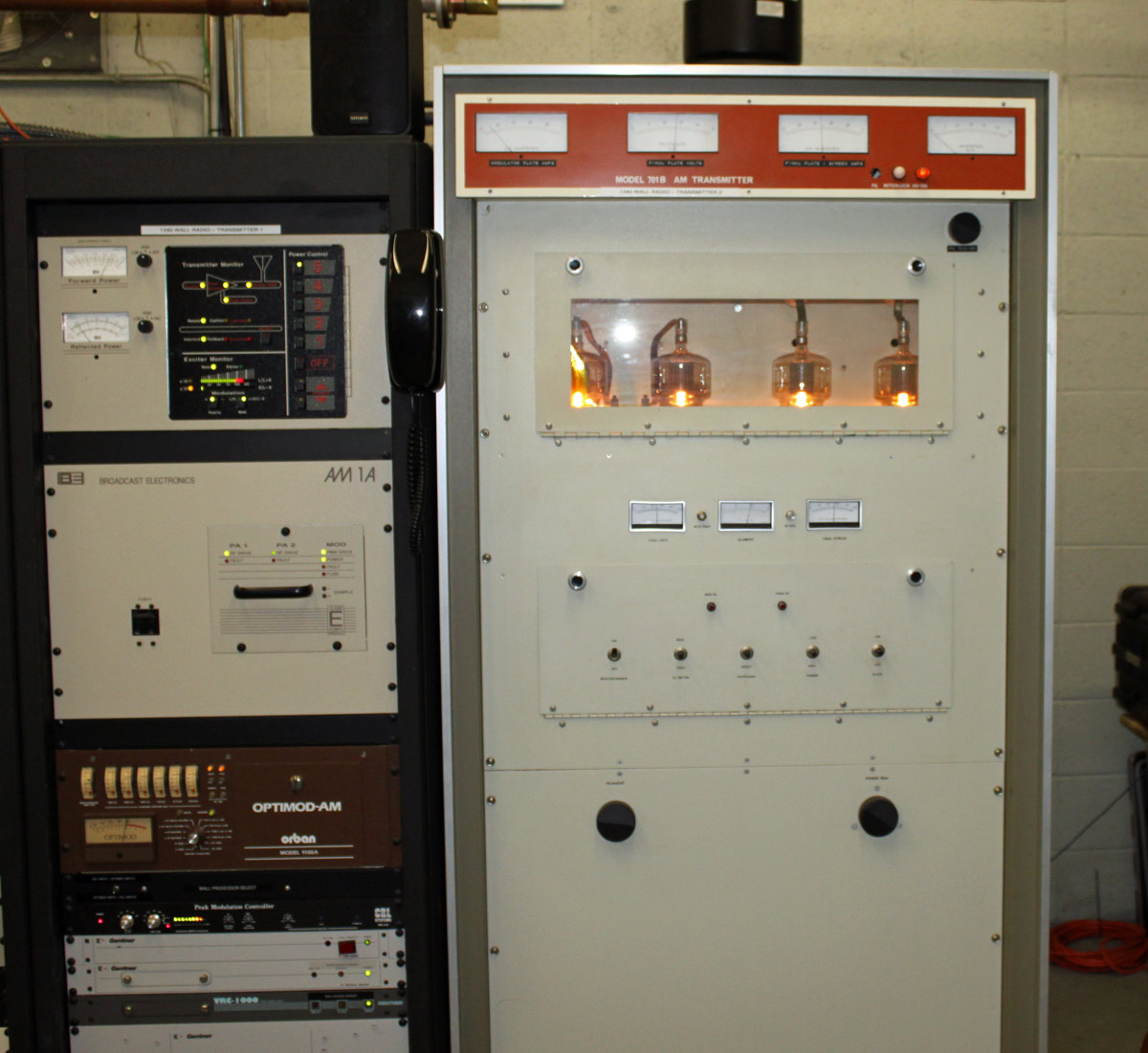
AM licensees are on their own, but all is not lost. I have noticed several successful stand-alone AM stations that are not only surviving but thriving. The common thread in this station is good local programming. On the technical side of things; a well-maintained plant with good quality audio feeding a properly operating transmitter and antenna array will go a long way to providing good service to the city of license.