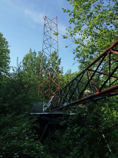
This is a tower behind one of our FM transmitter sites. In the past, it has housed paging and two-way services. It has always been sort of a slum, in my opinion. Several times, malfunctioning or improperly installed 900 MHz paging radios from this site have caused interference with our 950 MHz STL receivers. In recent years, all those things have gone away, however, to be replaced by a Wireless Internet Service Provider (WISP). Even with this change, the site is mostly overgrown and uncared for.
Yesterday, I noticed the tower was not as tall as it used to be, so I walked down the hill and saw this:
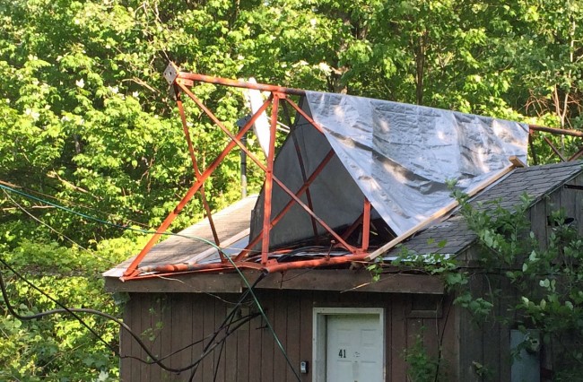
It appears this happened a few weeks ago. View from the other side:
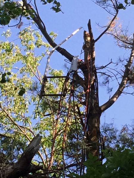
Close-up of the tower section that failed:
Looks like the bolts that held one of the flanges together failed, the tower was pushed over by a strong NE wind causing the other two legs to fail. Truth be told, the tower had been in rough shape since the mid-’90s. I am surprised that it stayed up this long.
WISP sector antennas. I don’t know if they owned the tower or were tenants. Either way, this is going to cost a few rubles to repair.
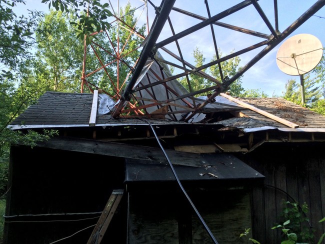
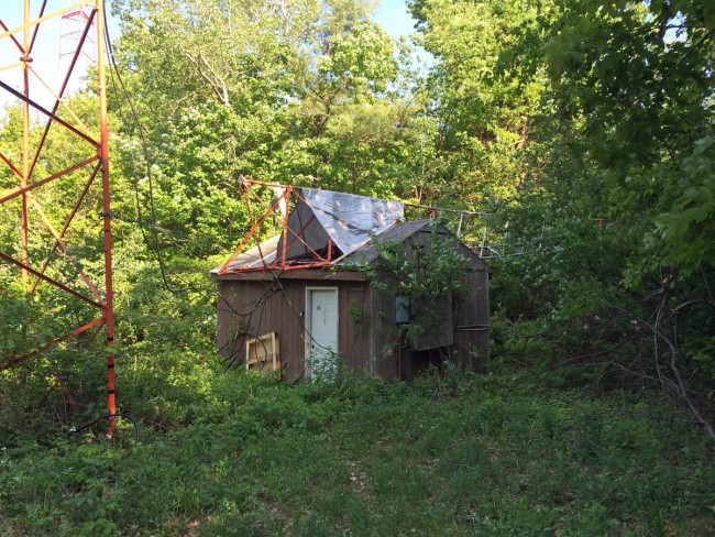
Looks like the shelter took a little bit of damage too. To be honest with you, I hope that this is it for this site. It would be nice if they take down the stump, scrap the lot of it and move it somewhere else.