There is some disagreement in the organization that I work with regarding the use of Shielded Cat 5e cable. Is it needed and if so, when and where? Category cables commonly used in Ethernet computer networks and also used for analog audio and other data applications come in a variety of flavors. Shielded (Shielded Twisted Pair or STP) and unshielded (Unshielded Twisted Pair or UTP) Cat 5, 5e, and 6 are the most common in radio broadcast facilities.
The main purpose for using UTP and STP for high-speed data transmission is common-mode rejection. Cables that are installed in office buildings are subject to various electric and electronic noise sources. Properly installed UTP works to reject these unwanted signals by using differential signaling, which is balanced. Differential signaling can best be described as transmitting information using two complementary signals that are opposite from one another.
The key performance measurement in category cable is Common Mode rejection. Outside noise will introduce a common mode signal on the cable which will be canceled out by the differential amplifier on the receiving end of the circuit. Proper terminations and good wiring techniques are very important for proper performance.
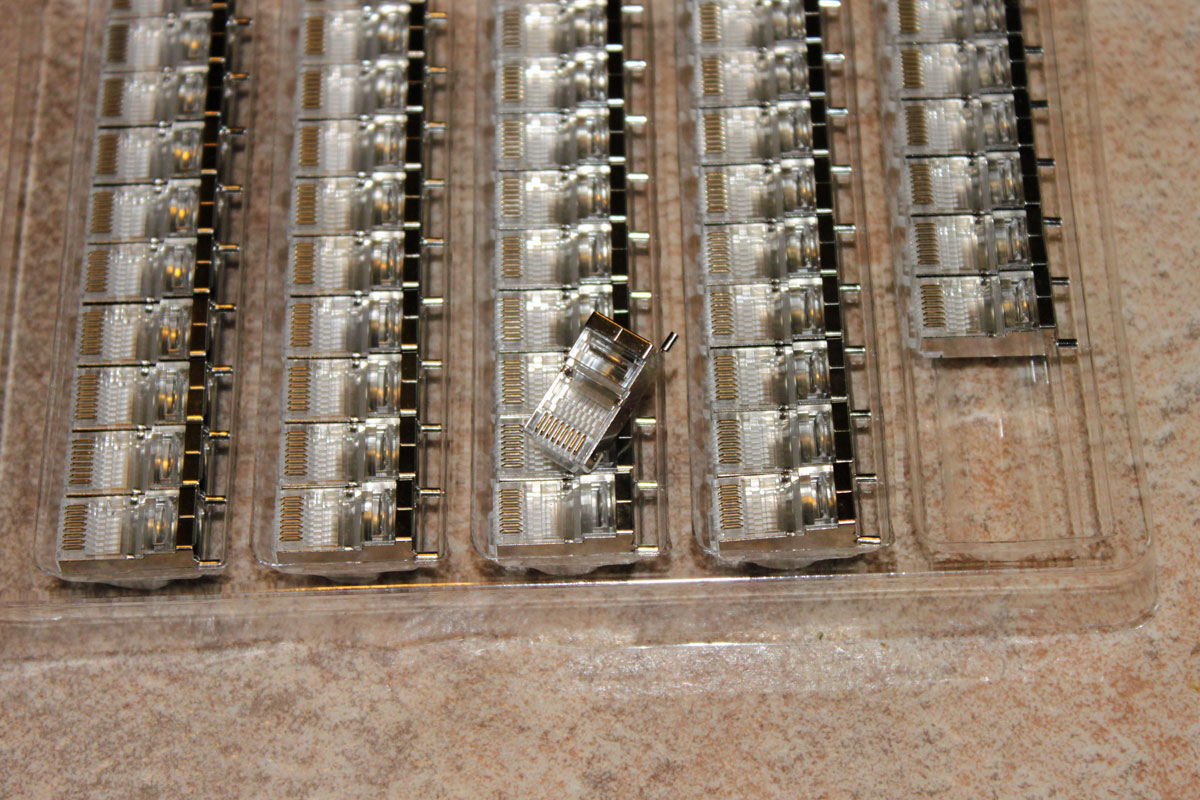
Using the correct patch panel termination, terminating block or RJ-45 (8P8C) connectors are required to maintain the advertised bandwidth of the cable. There is also a difference in the connector and terminating block designs for solid versus stranded cables. Using improper connectors for the type of cable installed can cause dropouts and loss of data.
When installing category cable, care must be taken not to kink the cable, not to exceed the recommended minimum bending radius, or exceed the maximum pulling force. Each of these will degrade the cable performance by changing the physical characteristics of the cable. Each pair of wires in category cable has a different twist. Altering these twist ratios by stretching the cable or bending it too sharply will increase the NEXT (Near End Cross Talk) and FEXT (far end cross talk) between pairs. In Gigabit networks, this will degrade throughput and create bottlenecks.
Generally speaking, the minimum bending radius is four times the cable diameter, or approximately one inch for Category 6 cable. The maximum pulling tension is not more than 25 ft/lbs or 110 Newtons.
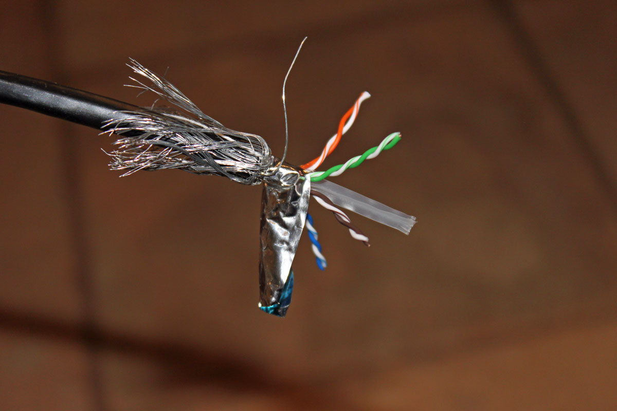
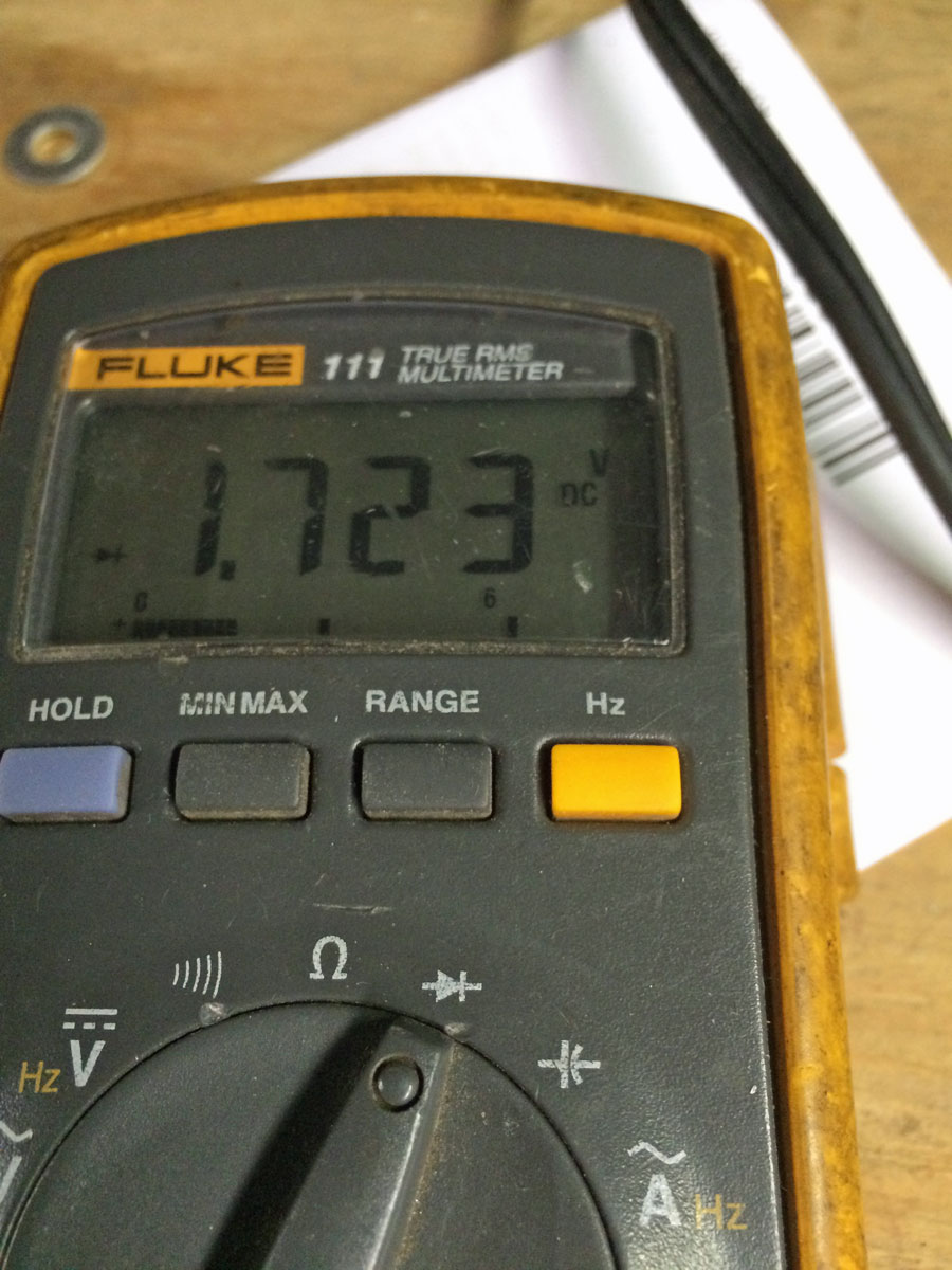
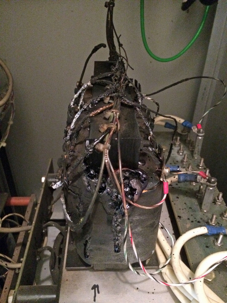
In high EMF environments, shielded cable (STP) can be beneficial in mitigating high electrical noise along with the proper installation techniques noted above. Signaling levels on 100BaseT are +1, 0, and -1 volt (MLT-3 Encoding). On Gigabit Ethernet, the levels are +1, +0.5, 0, −0.5, and −1 Volt (PAM-5 Encoding). Induced voltages on cables from external sources can degrade network performance and create bottlenecks. High EMF environments would include places like transmitter sites and anything on a tower or rooftop. Properly terminated shielded cable is necessary for EMP protection from lightning strikes or other sources. STP has special shielded metal connectors which each category cable class. These connectors supply the path to the ground through the RJ-45 jack.
Ungrounded shields are useless.
There are also other cable characteristics to consider such as UV-resistant jacking for outdoor installations or gel-filled (AKA “flooded”) cable for wet locations. Fortunately, there are plenty of sources for these types of cables and they are not terribly expensive.
To answer the question at the beginning of the post; STP can be beneficial at high EMI/EMF or RF sites to mitigate induced voltages on the cable from external sources provided it is properly terminated. In office and studio locations that are not at or next to a transmitter site, UTP is more than adequate provided it is properly installed and terminated.