The ability to do a Distance to Fault Measurement can greatly speed up the troubleshooting of potential antenna and/or transmission line problems. DTF measurements take on one of two forms; Time Domain Reflectometry (TDR) and Frequency Domain Reflectrometry (FDR).
TDR is the traditional method of measuring Distance to Fault. The test equipment sends short DC pulses down the cable and measures any return loss or SWR. Energy reflected back toward the instrument will plotted based on the time difference between the transmitted signal and the received reflection, similar to RADAR. This works well finding opens or shorts, but may not see lesser faults that could still be causing problems.
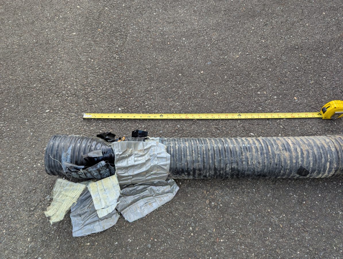
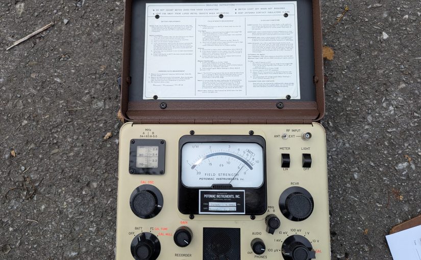
FDR is now common in most field models of Vector Network Analyzers. An FDR sends a frequency sweep down the cable then uses an Inverse Fast Fourier Transform (FFT) function to convert the information into a time domain. FDR can more reliably detect smaller issues with cables such as kinks, sharp bends, water in the cable, poorly applied connectors, or bullet holes. The piece of dented cable above would not have given a large reflection on a TDR, but on an FDR it would show up very nicely.
Like a VNA, an FDR needs to be calibrated for the sweep frequencies in use. The frequency span or bandwidth of an FDR has a major role in DTF measurements. A wider span will result in more precise fault information, however, it will reduce the over all length that the instrument can test. For most broadcast RF applications, cable lengths are less than 670 meters (2200 feet). Many instruments will adjust the maximum distance automatically based on the chosen span and velocity factor.
For my equipment, a Siglent SVA 1032X, the maximum distance for any frequency span can be found with this formula:
Maximum Distance (meters) = 7.86 x 10⁴ x Velocity Factor/Span (MHz)
Thus, to get best resolution sweeping a cable that is 670 meters long with a velocity factor of 86%: 7.68 x 10,000 x .86 / 95 MHz = 695 Meters maximum distance.
The resolution for any frequency span can be calculated with the following formula:
Resolution (meters) = 1.5 × 10² × velocity factor/Span (MHz)
In this case, the resolution would be +/- 1.35 meters. For shorter cable lengths a larger span can be used for better resolution.
My preference is to center the sweep frequency around the channel or frequency of the system under test.
To use a DTF function, a few inputs are needed:
- The velocity factor of the transmission line
- Cable attenuation for the swept frequency in dB/Meter
- The approximate length of the line under test
The cable velocity factor and attenuation can be obtained from the manufacturer’s data sheet. Keep in mind that the manufacturer’s data is an estimation. These are usually pretty close to the actual number, but may vary due to tight bends in the cable, any splices, transitions to different cable, etc.
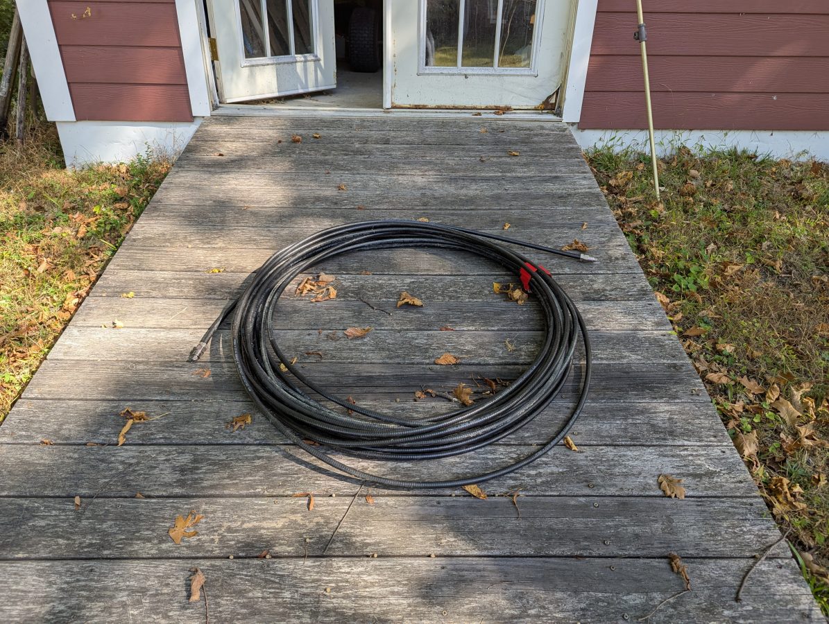
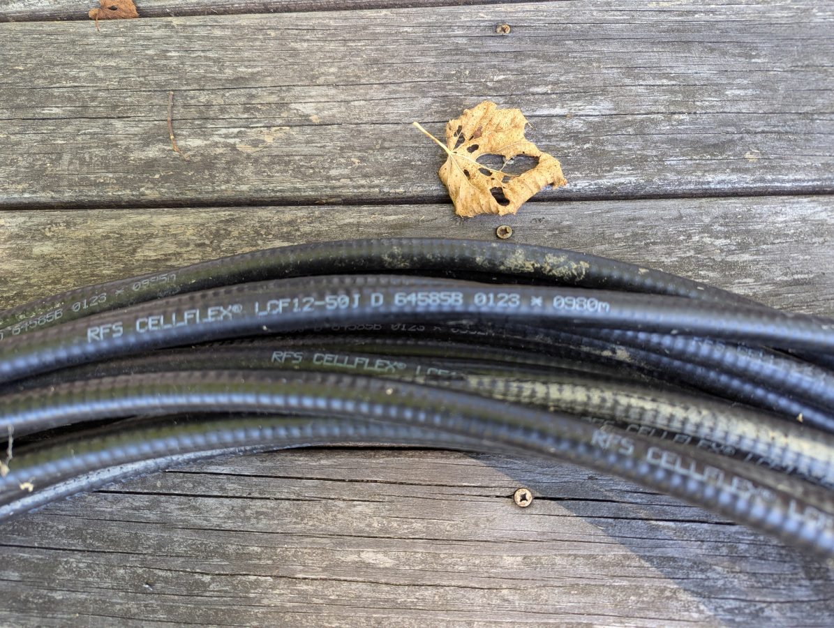
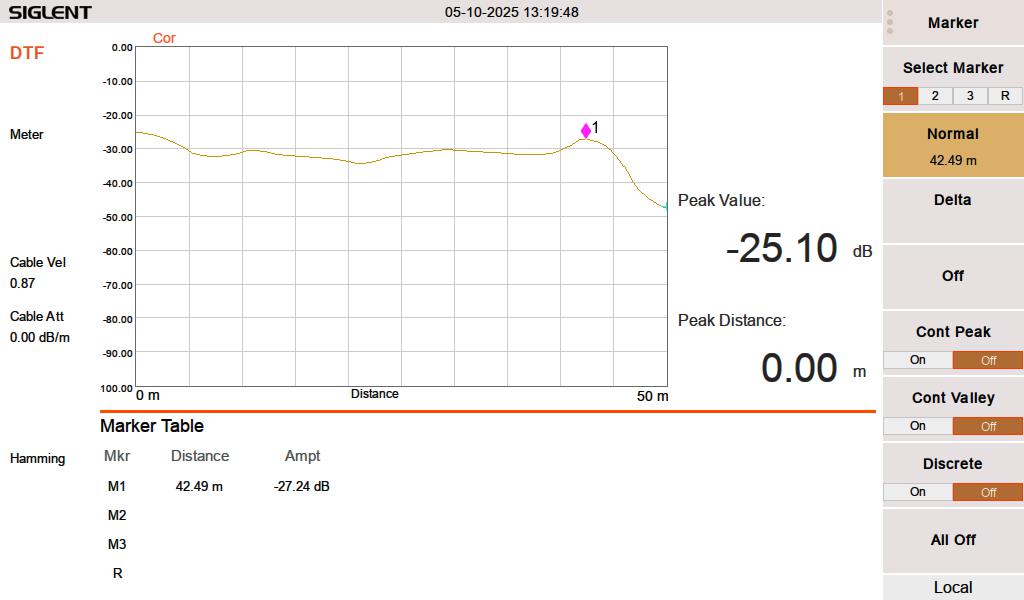
I had this used 1/2 inch RFS LCF12 50J cable in the barn, left over from project. Fortunately this is newer cable and it had the length marked out in meters. The beginning number was 0980 meters, the end was 1021 meters. Each meter marking has an asterisk before the number. I used a meter stick to measure out the distance between the asterisks and they are exactly one meter apart. I then measured the distance between the asterisk and the connector on each and ended up with 1.49 meters (4.9 feet) additional length, making the total length 42.49 meters (139.4 feet). The manufacture’s specification on velocity factor is 0.87 or 87% of the speed of light.
When I test this line with a 50 termination, it looks like this:
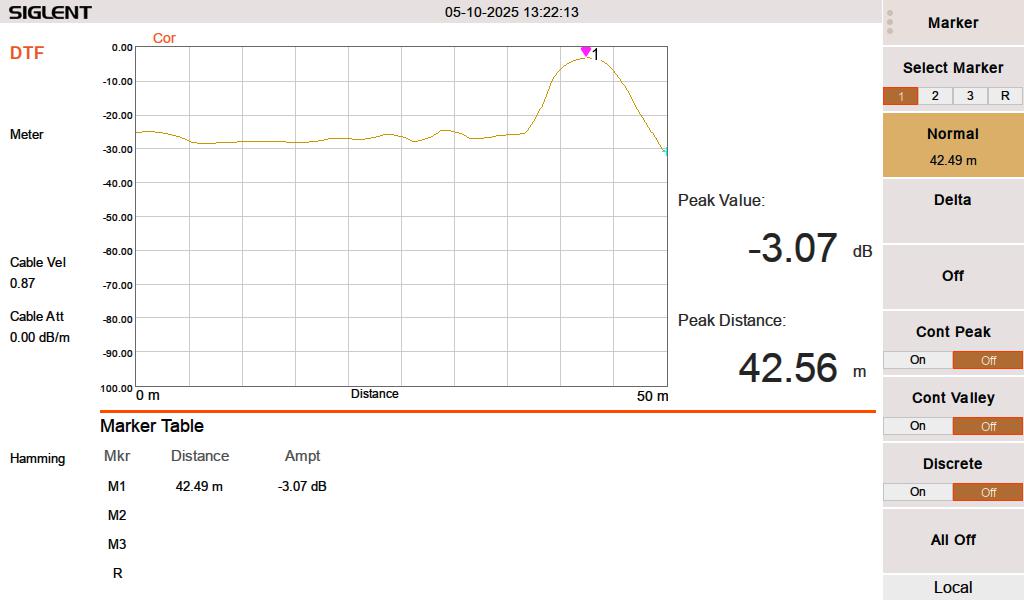
When I test the line either open or shorted, it looks like this:
I swept the cable at HF frequencies (3-30 MHz) since I think that is what this is going to be used for. At 3 MHz, the cable has a loss of approximately 0.003 dB per meter, which is inconsequential for this test. The velocity factor of 0.87 is pretty close. A longer run might indicate that it is actually 0.875 or 0.88.
Velocity factor and cable impedance are very important when using the Moment of Methods (MOM) system for AM antenna work. In that situation, both need to be obtained with a VNA for the FCC application.
The best practice is to sweep into a terminated line. In an AM system, a termination can most often be applied at the ATU input J plug. Sweeping into an antenna is possible, however there are several things that may lead to poor results. Most often, an FM antenna will look like a short on a DTF measurement. A UHF slot antenna will look open. In addition to that, the DTF measurement may be corrupted by any signals being received by the antenna while the system is under test.