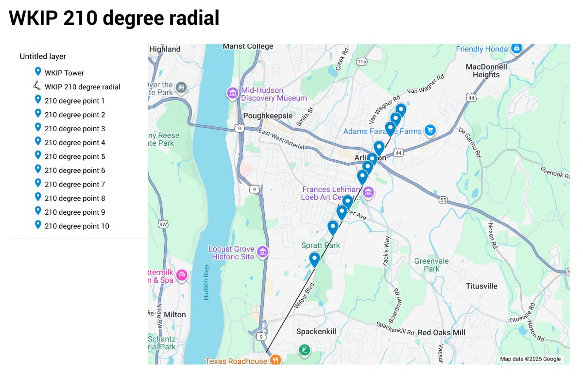
I have been finishing up a project which required detuning a new monopole installed near an AM tower. One requirement was a series of field strength measurements along six evenly spaced radials around the AM tower. The point is to see if there is any effect in the omni-directional AM signal (there should not be).
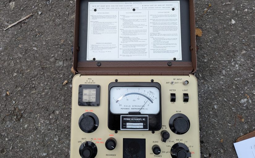
For this, I used the venerable Potomac Instruments FIM-41. As I recall, these units are rather pricey. The frequency range is 0.5 to 5.0 MHz. The basic measurement unit is a Volt/Meter, which is an electric field measurement. Something that measures 1 V/M means that the electric potential between two objects 1 meter apart is 1 volt. The meter will also make measurements in dBm, which is a logarithmic electromagnetic field strength measurement.
Before making any measurements, it is a good idea to check the batteries. Also, the hinged lid part is a loop antenna and there are several contact fingers which can get a little dirty which may effect the measurement accuracy. These should be cleaned off with some alcohol and a q-tip. I have also seen a pencil eraser used.
The directions for meter calibration are on the inside of the lid. Even though I have done this type of measurement a thousand times, I always do a quick read through the directions just to make sure I don’t skip any of the steps. Depending on the power of the signal being measured, I like to calibrate the meter at least a mile or so away from the AM antenna system.
Check the battery with the function switch in the Batt position. The meter should read within the Batt range
Tune the signal with the function switch in the FI-Cal-Tune position. This should be done at some distance away from the antenna system. Tune for maximum meter reading.
Rotate the FIM until the signal is below 10 mV/M, switch the full scale switch to CAL and adjust the CAL OSC for maximum meter reading.
Switch the Function switch to CAL NULL and adjust the GAIN control to minimum meter reading.
To take readings put the function switch in CAL TUNE and the Full Scale switch at whichever position results in an on scale reading. On less one of the knobs gets bumped, the meter only needs to be calibrated once.
Measurements should be made three or more hours after local sunrise and three or more hours before local sunset. This is to prevent other sky wave signals from interfering with the measurements. The first measurement should be greater than five times the tower height, in this case more than 240 meters.
I used Google Maps to generate a set of points along each radial then noted the coordinates and a brief description on a spread sheet. Since everything was on Google Maps, it was easy to navigate from one point to the next:
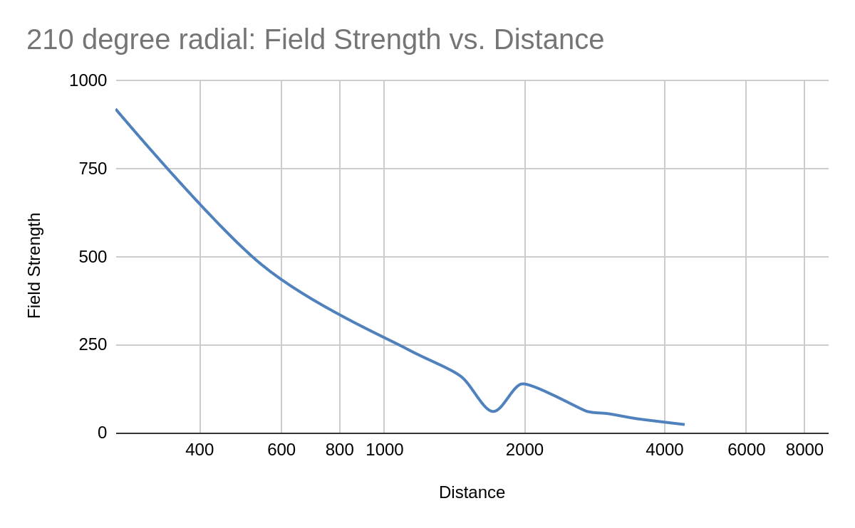
Field strength readings follow the inverse square law. Whatever the increase in the distance factor from the radiator, the electrical field will decrease inversely by the square of that factor. Thus, if the distance increases by 3, the field will decrease by a factor of 9.
This can be seen in a field strength vs distance graph which I plotted on an Excel spreadsheet:
Field strength in mV/M, distance in Meters
You can see around 2 KM away, there is something re-radiating the signal. This was near a college campus with lots of vertical metal structures around. There are two readings which should probably be thrown out to smooth out the curve.
At one point, further out along this radial, my car was attacked by a Rottweiler. The dog owner just stood in his front yard and watched it happen. After he got the dog back under control, I rolled my window down and told him what I thought of his dog. It is for this reason, I have a dash camera in my work vehicles. Too many times things happen while driving.
I pulled this out of the published posts and updated it.
I have been working on updating some wiring at one of our client’s transmitter sites. I noticed that an off air monitor feed was going back to the studio on a Barix box, which is fine. It was being fed from a balanced output of a DA to the unbalanced input on the Barix box. This being at the transmitter site, was susceptible to RF noise. I decided to make a passive audio BALUN.
Balanced to unbalanced audio converter using 10K to 600 ohm transformer
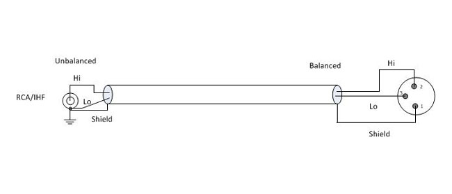
In any case, there are several ways to go from balanced to unbalanced without too much difficulty. The first way is to wire the shield and Lo together on the unbalanced connector. This works well with older, transformer input/output gear, so long as the unbalanced cables are kept relatively short.
simple balanced to unbalanced audio connection
Most modern professional audio equipment has active balanced input/output interfaces, in which case the above circuit will unbalance the audio and decrease the CMRR (Common Mode Rejection Ratio), increasing the chance of noise, buzz, and so on getting into the audio. In this case, the CMRR is about 30 dB at 60 Hz. Also, newer equipment with active balanced input/output, particularly some brands of sound cards will not like to have the Lo side grounded. In a few instances, this can actually damage the equipment.
A Henry Match Box or something similar can be used. I have found, however, the active components in such devices can sometimes fail, creating hum, distortion, buzz, or no audio at all. Well-designed and manufactured passive components (transformers and resistors) will provide excellent performance with little chance of failure. There are several methods of using transformers to go from balanced to unbalanced or vice versa.
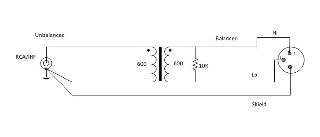
Balanced to unbalanced audio using 1:1 transformer
Using a 600:600 ohm transformer is the most common. Unbalanced audio impedance of consumer-grade electronics can vary anywhere from 270 to 470 ohms or more. The 10,000-ohm resistor provides constant loading regardless of what the unbalanced impedance. In this configuration, CMMR (Common-Mode Rejection Ratio) will be 55 dB at 60 Hz, but gradually decreases to about 30 dB for frequencies above 1 KHz.
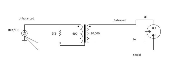
Balanced to unbalanced audio using a 4:1 transformer
A 600:10,000 ohm transformer will give better performance, as the CMMR will be 120 dB at 60 Hz and 80 dB at 3 KHz, remaining high across the entire audio bandwidth. The line balancing will be far better for the high-impedance load. This circuit will have about 12dB attenuation, so plan accordingly.
For best results, use high-quality transformers like Jensen, UTC, or even WE 111C (although they are huge) can be used. I have found several places where these transformers can be scrounged, DATS cards on the old 7300 series Scientific Atlanta satellite receivers, old modules from PRE consoles, etc. A simple audio BALUN can be constructed for little cost or effort and sound a whole lot better than doing it the wrong way.
A brief list, there are other types/manufacturers that will work also:
Ratio
Jensen
Hammond
UTC
Edcor
1:1 (600:600)
JT11E series
804, 560G
A20, A21, A43
PC600/600
4:1 (10K:600)
JT10K series
560N
A35
PC10K/600
Keep all unbalanced cable runs as short as possible. In stereo circuits, phasing is critically important, so pay attention to how the balanced transformer windings are connected.
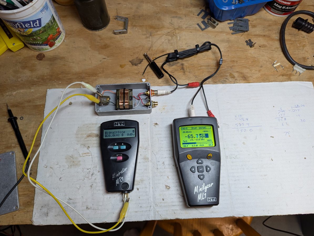
Device Under Test; THD at 20 KHz
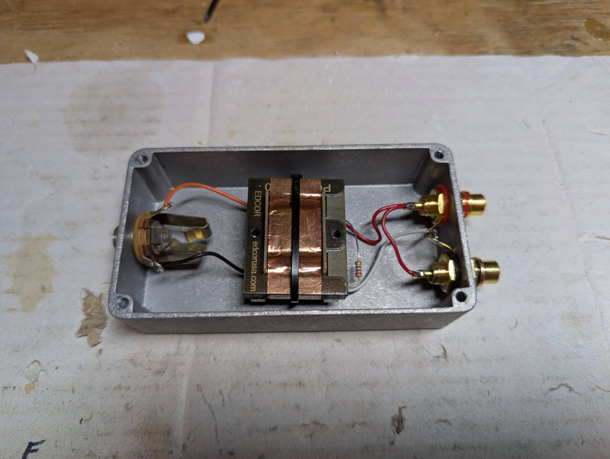
As for cost; I purchased the Edcor PC10K/600 transformer on eBay for $20.00 and the Hammond 1590B Enclosure was about $9.00. The audio jacks and resistor were in the parts drawer. It took about 20 minutes to layout the holes, drill, mount the audio jacks, and solder the jumper wires. I used a tie-base, wire tie, and some Gorilla glue to hold the transformer down. I used a 1/4 inch TRS jack because the enclosure was a little bit too small for an XLR jack. If a stereo pair needed be converted, it would require two of everything.
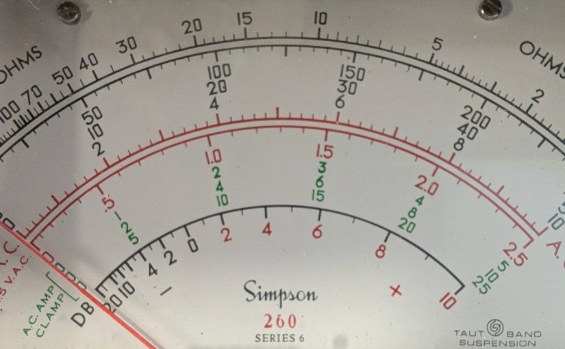
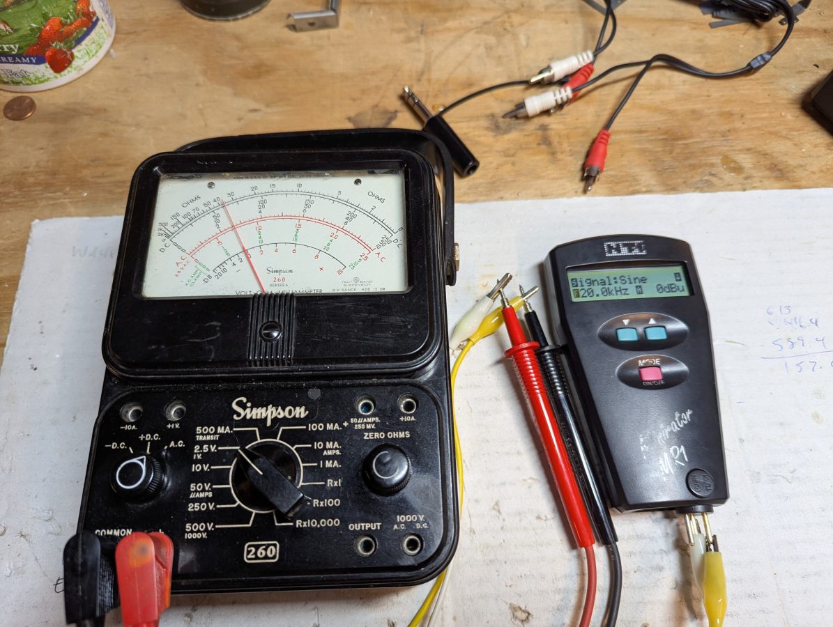
Overall, I fun project. The old Simpson 260 is still accurate!
Checking the accuracy of a Simpson 260 on audio frequencies.
This does not have much to do with Broadcast Engineering.
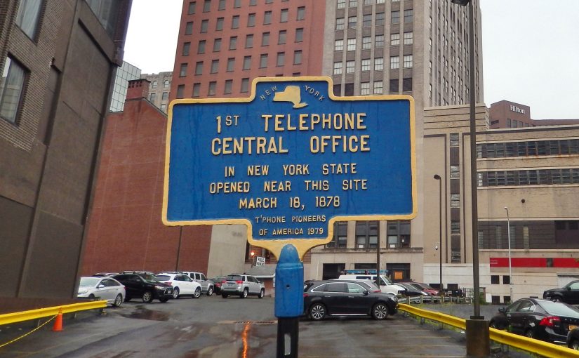
Recently, I saw a video about an engineer in Vermont who was fixing and placing single slot pay phones at welcome centers around the state. These are functioning as courtesy phones for travelers to use, free of charge. That is an interesting project.
My father worked for New York Telephone Company in various capacities from 1954 until he retired in 1988. We had a number of old telephone sets around the house which were removed from homes, old farms, businesses, and the like. One such telephone was a three slot pay phone from The Hitchcock estate in Millbrook, NY. This was a very unique item, as it dated from the Timothy Leary period of residence. It had white, blue, pink, and purple swirls painted all over it. At some point, G. Gordon Liddy, who was the then assistant District Attorney for Dutchess County, rented a Cessna and flew over the house to obtain a search warrant. After Leary was arrested, the group of LSD experimenters living in the estate house soon dissipated. My father went in and removed the pay phone. He said that those folks were living in squalor, “like filthy animals.” In fairness to my father, his Korean War experience while serving in the Marine Corps may have slightly colored his opinions about such things.
We called it the “hippie phone.” I believe it was a Western Electric model. After I moved out of the house I grew up in, all of those things disappeared.
I would have liked to have kept that pay phone.
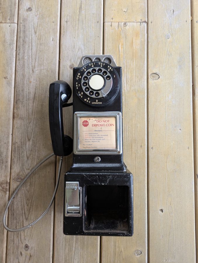
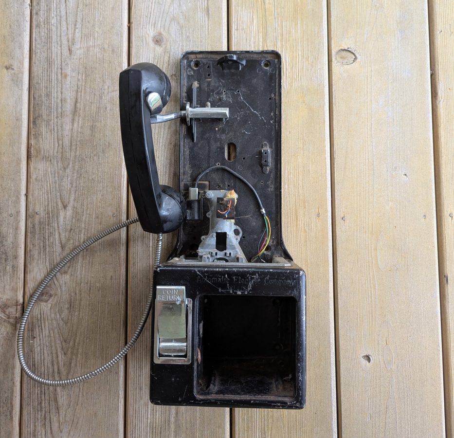
All of that got me thinking about pay phones. Could there possibly be a similar pay phone for sale on eBay? Yes, there could. But they all seemed terribly expensive. Except for one reasonably priced unit, which I purchased. This is an Automatic Electric pay station, which is almost identical looking to the Western Electric unit from the same era.
Automatic Electric 3 slot pay station
When it arrived, I discovered the reason why it was less expensive; it is missing all of the internal parts. I was a little irritated by this, but soon discovered that it was typical. The phone company often removed the coin collecting relay and vault door as soon as the phone was taken out of service. The hook switch, induction coil, condenser, terminal board, and wiring harness were all removed, probably to be used to restore another phone.
No internal parts
Fortunately the coin slot and coin validating mechanism are still in place. If you drop a dime you will hear a nice “ting ting.” A nickle will result in a single “ting,” a quarter will make a satisfying “bong” sound from the gong.
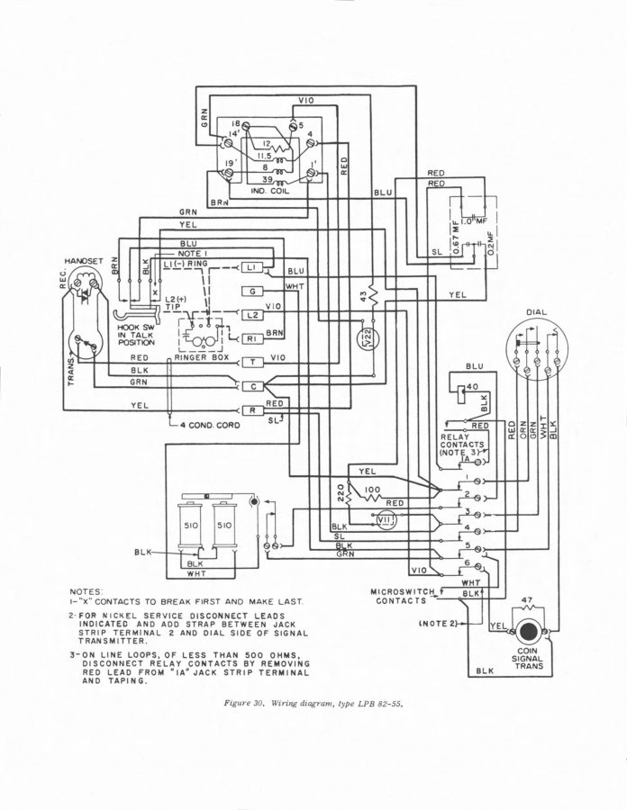
I found a manual on line for the Automatic Electric pay phones which had a wiring diagram with the wire colors.
Automatic Electric 82-55 wiring diagram
Unfortunately, there are no part numbers. I had a difficult time trying to figure out the correct parts to search for. I finally stumbled upon a Youtube video where someone was tearing down one of these units. That revealed the OEM part numbers for the coil (D284476A) and condenser (D68850A). With that, I was able to find the original manufacture’s assembly which included the hook switch, induction coil, wiring harness and terminal strip for a reasonable price on The Old Phone Shop website. I also ordered the condenser and a ringer (these phone had no internal ringers as manufactured). There is an option to buy an entire modern network board, but I wanted to keep this as original as possible.
The wire harness from the rotary dial was also missing. I used some wire from Belden 9423 cable to make those connections, keeping the wire colors shown in the schematic.
Next, I purchase a Pulse Dial to Touch Tone Converter. On POTS lines, most CO switches still recognize pulse dialing. However, POTS lines are expensive and I do not want to pay for one at my house. The answer is an Analog Telephone Adapter (ATA) with this converter. I purchased a Cisco/Linksys 2102 unlocked ATA on eBay for $16.00. Lowest cost DID number I could find is about $8 – 9 per month. There are directions on how to DIY a pulse dial to touch tone converter, but I simply purchased one on Amazon.
A bit about Plain Old Telephone Service (POTS) lines. It is a circuit switched data system. These systems are very simple and consist of a two wire circuit between the Company Office (CO) and subscriber Point of Presence (POP) known as a local loop or subscriber loop. The circuit is made by closing the Hook Switch. When the circuit is open, there is nominally -48 VDC across the Tip and Ring. When the Hook Switch closes (goes off hook), that drops to about 7-9 VDC. When the circuit closes, the CO switch detects a current flow and puts a Dial Tone consisting of two tones, 350 Hz plus 440 Hz on the loop. The subscriber can then dial a number and be connected to another party through the switch and what ever local or long distance carriers are needed to complete the call. On the other end, the CO switch will put a 20 Hz 90 VAC ring voltage down the line to ring the receiving subscriber’s phone. If the distant station is already off the hook, a busy signal is sent to the call originator, consisting of 480 and 640 Hz tones.
Internal to every POTS phone is a network consisting of an inductive coil and a capacitor or two and a resistor or two. The purpose of this is for line equalization and to create a two wire to four wire hybrid. The four wire hybrid is what feeds audio to the ear piece and receives audio from the handset microphone. It cancels echo from the distant station and provides a small amount to “side tone” or audio from the microphone so the user can hear themselves when they talk. The audio pass band is from about 300 Hz to 3,300 Hz.
In addition to that, some type of dial mechanism is required; either pulse or DTMF (Dual Tone Multiple Frequency). Pulse dial interrupts the closed Hook Switch in rapid succession (39 ms on, 61 ms off) to send a number to the switch at the CO.
DTMF consists of the following tone pairs:
Number
Tones (Hz)
Number
Tones (Hz)
Number
Tones (Hz)
1
697, 1209
2
697, 1336
3
697, 1447
4
770, 1209
5
770, 1336
6
770, 1447
7
852, 1209
8
852, 1336
9
852, 1447
*
941, 1209
0
941, 1336
#
941, 1447
Provided the local loop stays intact, the POT system is extremely reliable.
The Analog Telephone Adapter (ATA) converts a POTS from a circuit switched system to a packet switched system, then uses the public internet to complete a call. ATAs do not accept pulse dialing, hence the Pulse Dial to Touch Tone Converter. Where ATAs often fail is the ring voltage and tip/ring polarity.
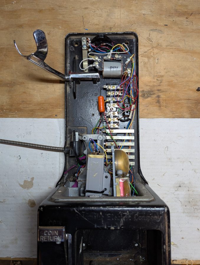
Back to the task at hand: When the parts arrived, they all matched the mounting holes in the back plate of the phone. That is a good sign. I took the rotary dial off and put the new wires on. I also took the time to de-gunk and clean the mechanical parts of the rotary dial, then re-oiled it. It works as well as the day it was manufactured. The old mechanical phone system parts were built to last a long, long time.
The Hook Switch, Terminal Board, harness and condenser all fit into the phone almost perfectly. The condenser was hitting against the coin validator which didn’t seem quite right. I moved the condenser down to where the coin relay was located so it didn’t get scratched up.
Automatic Electric 3 slot pay station with parts installed
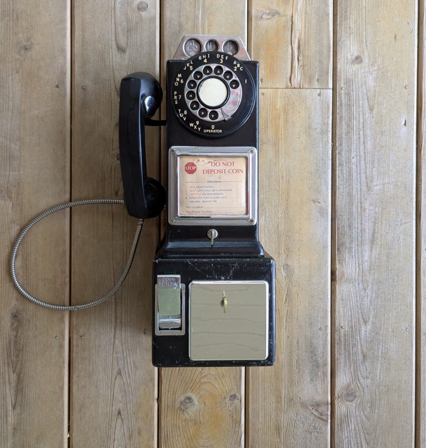
I also bought a small ringer, which I installed where the coin relay was. I purchased a replacement vault door and lock. This is a plastic unit, not a OEM part, however, it does the job and I am not worried about anybody prying the vault door off and stealing all the change. Putting it all together, it looks great! Now I need to find a used phone booth to put it in. There are a few of those on eBay as well, but very pricey.
Automatic Electric 3 slot pay station, restoration complete
I took the phone to the office and plugged it into a POTS line and called my cellphone. The old carbon element microphone might need to be replaced, other than that, everything works great. It is now worth considerably more than I paid for it, which is also nice.
W277CJ, Pittsfield was originally a translator for WUPE-AM 1110 KHz. Since that license has been surrendered to the FCC, it is now a translator for WBEC-FM HD2 which is simulcast of WUPE-FM, North Adams.
Confused yet? Don’t worry, it is a reshuffling of signals because the land under the 1110 KHz transmitter site was sold and the license turned in to the FCC. Something that I think will happen many more times to many more stations in the coming years. This translator was first put on the air in June of 2015. This is the third part of a series, the first two parts are: More AM work, Part V and The Bext TFC2K broadband antenna.
Equipment Removed
The translator recently moved it off of the Holiday Inn (formerly Crown Plaza) in downtown Pittsfield, MA to the WBEC AM tower. In order to make that move, we needed to do several things;
“sufficient measurements shall be made to establish that the operation authorized in this construction permit is in compliance with the spurious emissions requirements of 47 C.F.R. Sections 73.317(b) through 73.317(d). All measurements must be made with all stations simultaneously utilizing the shared antenna.”
These are intermodulation products, or third order products, between the two signals being transmitted, in this case W277CJ on 103.3MHz and WUPE-FM 95.9 MHz. The antenna side mounted on the AM tower serves as a back facility for WUPE-FM.
WBEC-FM backup and W277CJ connected to Bext FDCSDC-2 combiner
Those measurements are as follows:
(F1-F2) + F1 or (103.3 MHz – 95.9 MHz) + 103.3 MHz = 110.7 MHz
In order to make those measurements, I used two Microwave Filter Company MFC-6367 notch filters to attenuate the carriers on 95.9 and 103.3 MHz. This keeps the spectrum analyzer from overloading, thus lowering the analyzer noise floor and giving better results.
Various tools for proofing FM installations
Over the years, I have collected various parts to assist in getting good measurements for FM proofing. Going clockwise and starting at the top, the Rhode Schwarz NRP-Z11 power sensor, the MFC-6367 FM notch filters, directional couplers with power extractor element, various attenuators including the HP 255C variable 0-12 dB unit, and in the middle are two Mini-Circuits NHP-200+ high pass filters. The high pass filters are great for measuring harmonics.
W277CJ – WBEC-FM test setup
To measure the third order products noted above, I first measured the carrier without the filters and an appropriate pad to get a carrier reference level. Then installing the MFC-6367 filters to measure the third order products. In addition to that, harmonics of both FM transmitters out to the 10th harmonic. Of particular importance is anything in the cellular or mobile data bands. All of these measurements were well below the -80 dBc threshold required by the FCC.
All of these measurements were well within the limits established by FCC part 73.317.
Also, because this is mounted on an AM tower, there are some AM things that needed to be completed:
“The AM station identified below may be affected by the facilities authorized by this construction permit. Pursuant to Section 1.30004 of the Commission’s Rules, at least 30 days prior to commencement of construction of the facilities authorized herein, the permittee must provide notification of the construction to the AM station licensee. As part of this notification, the permittee must examine the potential impact of the construction of the authorized facilities on the AM station using a moment method analysis. The analysis shall consist of a model of the AM antenna together with the potential re-radiating tower in a lossless environment. The model shall employ the methodology specified in Section 73.151(c) of the Commission’s Rules, except that the AM antenna elements may be modeled as a series of thin wires driven to produce the required radiation pattern, without any requirement for measurement of tower impedances. If the AM station was authorized pursuant to a directional proof of performance based on field strength measurements, the permittee may, in lieu of the moment method analysis, demonstrate with measurements taken before and after construction that field strength values at the monitoring points do not exceed the licensed values.”
Since this station was proofed several times, we did about ten readings along the monitor point radials, both before and after.
The new isocoupler was properly mounted:
Kintronic broadband AM isocoupler
This is simply a large coil of 7/8 Coax wound inside of a PVC form.
These AM antenna systems are a regulatory nightmare. Although the Moment Method is an improvement over the system of field measurement proofs, it is still complicated. Part of the issue with AM in general is the expense of the the antenna systems, particularly anything that is directional.
No real research into Medium Frequency antennas and propagation has been done since the 1930’s. Perhaps we know all there is to know about it, then again, perhaps not. I am currently working on a project which will study Medium Frequency propagation, which I feel, is the first step into revisions of antenna design.