As promised, here is the AM transmitter site maintenance checklist. This is for a generic directional AM station with a backup transmitter, generator, and an RF STL.
Usual disclaimers apply.
AM site Maintenance checklist
Weekly Maintenance:
A. Visit site, Check following:
- Check critical transmitter values against last logged value
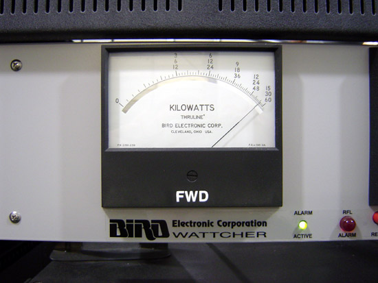
- Check forward/reflected power on main transmitter
- Check and reset any overloads
- Check signal strength on STL against last logged value
- Check generator fuel level
- General check of building, look in all rooms, inspect for damage from vandalism, Leaking roofs, obvious signs of trouble, take steps to correct.
Monthly Maintenance:
B. Visit site, Check following:
- Do a full multi-meter log, (includes tower phase angles, loop currents), run backup transmitter into dummy load.
- Start and run generator for 5 minutes, check block heater, hoses, belts, oil and antifreeze levels
- Calibrate remote control meters with transmitter meters, log it*
- Check all tower fences for integrity and locked gates*
- Complete Items 3, 4 and 5 under weekly maintenance.
Quarterly Maintenance:
C. Visit site, Check following:
- Complete 1 through 5 under monthly maintenance.
- Check all air filters, clean or replace as needed.
- Check frequencies of all transmitters, STL receiver, and log.
- Complete quarterly tower lighting and painting inspection*
Bi-yearly Maintenance:
D. Visit site, Check Following:
- Complete 1 through 5 under quarterly maintenance.
- Conduct monitor point readings for all directional antenna patterns*
- Check base current readings for day/night towers. Ratio.*
- Clean backup transmitter
- Place backup transmitter on air and clean main transmitter.
Yearly Maintenance:
E. Check all licenses and authorizations for accuracy. Make sure that all renewal cards etc are in public file and are posted at control point.*
F. Visit site, Check following
- Complete 1 through 5 under Bi-yearly maintenance
- Equipment performance measurements (NRSC, Harmonics, frequency)*
- Complete service of generator
- Complete Inspection of towers, check for vertical and plumb, check guy wire tensions, retension as needed.
- Check property for anything out of the ordinary
- Repair driveway as needed
General maintenance that is completed on an as needed basis
- Re-fill fuel generator fuel tank when drops below 50 percent
- Empty trash, sweep floors, dust.
- Cut/remove vegetation inside tower fences, spray herbicide as needed
- Water proof tower fences every 2 years
- Paint exterior of building
- Replace tower lights*
- Paint towers*
*These are FCC inspection items, pay close attention if you do not want a fine.
That is it, a .pdf version of this file can be downloaded here.