I always liked Gary Larson’s Far Side cartoons:

Perhaps it is not so funny…
I always liked Gary Larson’s Far Side cartoons:
Perhaps it is not so funny…
I recently got into an argument about the requirements for transmitter readings with a fellow engineer. Said fellow stated that transmitter readings need to be taken every three hours and that all operators needed to sign on and off the station log. Time was when those things were supposed to be done, that is true. I believe the rules have changed a little bit since he last read them. The current FCC rules (part 73.1820) state that the following items need to be in the station log:
The exception to this is AM stations without an FCC-approved antenna sampling system, which indeed require readings on the antenna system every three hours. Most AM stations have an approved antenna sampling system.
If an AM station has an approved sampling system, it will be noted on the instrument of authorization (license).
For transmitter operations, a review of part 73.1350 shows that the licensees are responsible for ensuring transmitting apparatus complies with all FCC regulations. Specifically:
73.1350 (b)(2)(c)The licensee must establish monitoring procedures and schedules for the station and the indicating instruments employed must comply with Sec. 73.1215.
And
73.1350 (b)(2)(c)(1) Monitoring procedures and schedules must enable the licensee to determine compliance with Sec. 73.1560 regarding operating power and AM station mode of operation, Sec. 73.1570 regarding modulation levels, and, where applicable, Sec. 73.1213 regarding antenna tower lighting, and Sec. 73.69 regarding the parameters of an AM directional antenna system.
One would assume that would mean some sort of logging. Further, a review of all recent NAL, NOV, and citations from the FCC’s enforcement bureau shows that field agents investigating a radio station will make their own power measurements if they suspect a broadcast station is operating out of power tolerance. Particularly with AM directional stations that are supposed to reduce power at night. I doubt very much that producing an operating log with in-tolerance power readings would do any good in those circumstances.
For directional AM stations that change power/mode at night, some routine of checking the transmitter for proper power levels after power/pattern change needs to be established. If there is an auto logging system, such as a Burk Autopilot, then checking that system for the proper time of day and/or proper pattern/power change functioning could take the place of checking the actual transmitter readings as long as there were an alarm (and notification) generated during an out of tolerance condition.
For most FM stations and AM non-directional stations, most modern transmitters have Automatic Power Control (APC) built in. As long as the APC is functioning properly and there is an alarm (with notification) generated when an out-of-tolerance condition occurs (under/over power), logging power output readings can be done on a weekly maintenance log.
Station logs are to be retained for two years (73.1840) and should be available to the FCC for inspection. After two years, throw the logs out because anything that you have on file is liable to be inspected. Any rule infractions found in the station logs can lead to an NOV or NAL, even if it happened more than two years ago.
For your reading pleasure:
73.1820
Sec. 73.1820 Station log.
(a) Entries must be made in the station log either manually by a
person designated by the licensee who is in actual charge of the
transmitting apparatus, or by automatic devices meeting the requirements of paragraph (b) of this section. Indications of operating parameters that are required to be logged must be logged prior to any adjustment of the equipment. Where adjustments are made to restore parameters to their proper operating values, the corrected indications must be logged and accompanied, if any parameter deviation was beyond a prescribed tolerance, by a notation describing the nature of the corrective action. Indications of all parameters whose values are affected by the modulation of the carrier must be read without modulation. The actual time of observation must be included in each log entry. The following information must be entered:
(1) All stations. (i) Entries required by Sec. 17.49 of this
chapter concerning any observed or otherwise known extinguishment or improper functioning of a tower light:
(A) The nature of such extinguishment or improper functioning.
(B) The date and time the extinguishment or improper operation was observed or otherwise noted.
(C) The date, time and nature of adjustments, repairs or
replacements made.
(ii) Any entries not specifically required in this section, but
required by the instrument of authorization or elsewhere in this part.
(iii) An entry of each test and activation of the Emergency Alert
System (EAS) pursuant to the requirement of part 11 of this chapter and the EAS Operating Handbook. Stations may keep EAS data in a special EAS log which shall be maintained at a convenient
location; however, this log is considered a part of the station log.
(2) Directional AM stations without an FCC-approved antenna sampling system (See Sec. 73.68). (i) An entry at the beginning of operations in each mode of operation, and thereafter at intervals not exceeding 3 hours, of the following (actual readings observed prior to making any adjustments to the equipment and an indication of any corrections to restore parameters to normal operating values):
(A) Common point current.
(B) When the operating power is determined by the indirect method, the efficiency factor F and either the product of the final amplifier input voltage and current or the calculated antenna input power. See Sec. 73.51(e).
(C) Antenna monitor phase or phase deviation indications.
(D) Antenna monitor sample currents, current ratios, or ratio
deviation indications.
(ii) Entries required by Sec. 73.61 performed in accordance with the schedule specified therein.
(iii) Entries of the results of calibration of automatic logging
devices (see paragraph (b) of this section) or indicating instruments
(see Sec. 73.67), whenever performed.
(b) Automatic devices accurately calibrated and with appropriate
time, date and circuit functions may be utilized to record entries in
the station log Provided:
(1) The recording devices do not affect the operation of circuits or
accuracy of indicating instruments of the equipment being recorded;
(2) The recording devices have an accuracy equivalent to the
accuracy of the indicating instruments;
(3) The calibration is checked against the original indicators as
often as necessary to ensure recording accuracy;
(4) In the event of failure or malfunctioning of the automatic
equipment, the person designated by the licensee as being responsible for the log small make the required entries in the log manually at that time;
(5) The indicating equipment conforms to the requirements of Sec. 73.1215 (Indicating instruments–specifications) except that the scales need not exceed 5 cm (2 inches) in length. Arbitrary scales may not be used.
(c) In preparing the station log, original data may be recorded in
rough form and later transcribed into the log.
73.1350:
Sec. 73.1350 Transmission system operation.
(a) Each licensee is responsible for maintaining and operating its
broadcast station in a manner which complies with the technical rules
set forth elsewhere in this part and in accordance with the terms of the station authorization.
(b) The licensee must designate a chief operator in accordance with Sec. 73.1870. The licensee may designate one or more technically competent persons to adjust the transmitter operating parameters for compliance with the technical rules and the station authorization.
(1) Persons so authorized by the licensee may make such adjustments directly at the transmitter site or by using control equipment at an off-site location.
(2) The transmitter control personnel must have the capability to
turn the transmitter off at all times. If the personnel are at a remote
location, the control system must provide this capability continuously
or must include an alternate method of acquiring control that can
satisfy the requirement of paragraph (e) of this section that operation
be terminated within three minutes.
(c)The licensee must establish monitoring procedures and schedules for the station and the indicating instruments employed must comply with Sec. 73.1215.
(1) Monitoring procedures and schedules must enable the licensee to determine compliance with Sec. 73.1560 regarding operating power and AM station mode of operation, Sec. 73.1570 regarding modulation levels, and, where applicable, Sec. 73.1213 regarding antenna tower lighting, and Sec. 73.69 regarding the parameters of an AM directional antenna system.
(2) Monitoring equipment must be periodically calibrated so as to
provide reliable indications of transmitter operating parameters with a
known degree of accuracy. Errors inherent in monitoring equipment and the calibration procedure must be taken into account when adjusting operating parameters to ensure that the limits imposed by the technical rules and the station authorization are not exceeded.
(d) In the event that a broadcast station is operating in a manner
that is not in compliance with the applicable technical rules set forth
elsewhere in this part or the terms of the station authorization, and
the condition is not listed in paragraph (e) or (f) of this section,
broadcast operation must be terminated within three hours unless antenna input power is reduced sufficiently to eliminate any excess radiation. Examples of conditions that require termination of operation within three hours include excessive power, excessive modulation or the emission of spurious signals that do not result in harmful interference.
(e) If a broadcast station is operating in a manner that poses a
threat to life or property or that is likely to significantly disrupt
the operation of other stations, immediate corrective action is
required. In such cases, operation must be terminated within three
minutes unless antenna input power is reduced sufficiently to eliminate any excess radiation. Examples of conditions that require immediate corrective action include the emission of spurious signals that cause harmful interference, any mode of operation not specified by the station license for the pertinent time of day, or operation substantially at variance from the authorized radiation pattern.
(f) If a broadcast station is operating in a manner that is not in
compliance with one of the following technical rules, operation may
continue if the station complies with relevant alternative provisions in
the specified rule section.
(1) AM directional antenna system tolerances, see Sec. 73.62;
(2) AM directional antenna monitoring points, see Sec. 73.158;
(3) TV visual waveform, see Sec. 73.691(b);
(4) Reduced power operation, see Sec. 73.1560(d);
(5) Reduced modulation level, see Sec. 73.1570(a);
(6) Emergency antennas, see Sec. 73.1680.
(g) The transmission system must be maintained and inspected in
accordance with Sec. 73.1580.
(h) Whenever a transmission system control point is established at a location other than the main studio or transmitter, a letter of
notification of that location must be sent to the FCC in Washington, DC, Attention: Audio Division (radio) or Video Division (television), Media Bureau, within 3 days of the initial use of that point. The letter
should include a list of all control points in use, for clarity. This
notification is not required if responsible station personnel can be
contacted at the transmitter or studio site during hours of operation.
(i) The licensee must ensure that the station is operated in
compliance with Part 11 of this chapter, the rules governing the
Emergency Alert System (EAS).
Another picture from my collection, this one is the back side of a power supply module from a Broadcast Electronics AM6A transmitter:
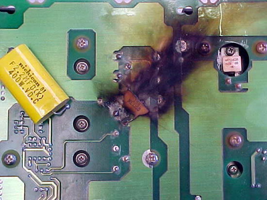
It happened during power up from 1 KW to 5 KW and it was quite loud, as I was standing right next to the transmitter. The exploded part is a 0.1 uf capacitor that looks like an add-on. In fact, some of the other power supplies don’t have it. It also took out the 20 amp slow blow fuse.
I like the exploded look of the board, kind of like on The Road Runner, when Wyle E. Coyote looks into a box and something explodes.
This is the only problem I have had with this particular transmitter.
Another example from my blown-up shit collection, pictures archive:
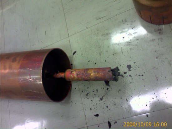
The harmonic filter from a Broadcast Electronics FM-30T. This actually started in the bullet connector to the 3-inch hardline on the output side of the filter.

Again, I did not install this myself, someone else did. Cutting 3-inch hard line is pretty straightforward. When using a field flange, the outer and inner conductors are cut flush. Both conductors should be de-burred and filed smoothly. It only takes a little thing to start an arc with 30 KW of FM power, so once again, attention to detail is key to avoiding these things.
Fortunately, BE sent along replacement parts for the harmonic filter and the line section was replaced.