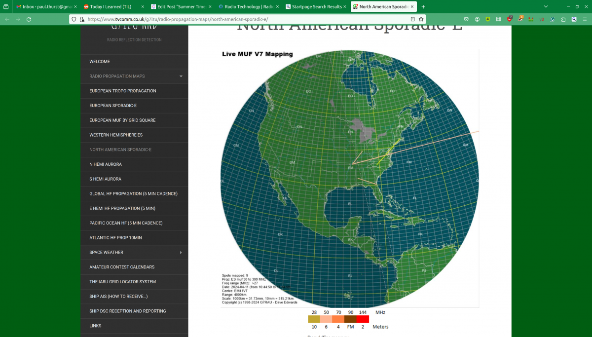
The largest problem facing analog AM broadcasting (and digital Medium Frequency and High Frequency broadcasting) is RF Noise.
Like most people, I have many modern conveniences that make my life easier than previous generations; electric lights, central heat and air conditioning, appliances like vacuum cleaners, microwave ovens, and whatnot. I enjoy the wireless internet, have an LED TV, use LED light bulbs, and get free electricity from my photovoltaic solar system. These devices can contribute to the high levels of RF noise found in most buildings. RF Noise which is the bain of AM broadcasting. Digital modulation schemes use variations in amplitude to transmit data bits. They are not immune to RF noise, they simply mask it better until they don’t.
I thought it would be interesting to isolate the various noise generators that may be present.
To make measurements, I used the Siglent SVA-1032X spectrum analyzer. This unit has a noise floor of -140 dB. My methodology is to turn everything off except the Device Under Test. Set the spectrum analyzer up for a wide band sweep, then narrow the bandwidth on any detected noise. Turn the DUT off to make sure that the noise goes away. Turn the DUT back on to make sure that the noise comes back.
The first thing I noticed; there is more noise during the daylight hours than at night. This is interesting. I thought it might be coming from my solar system, which uses individual inverters for each panel (so-called microinverters). These are wired to 240 VAC but have an internet gateway device that is in the house and communicates with the inverters using a power line data scheme. It turns out this was a minor contributor below the AM broadcast band.
By process of elimination, here are things that were not contributing to RF noise on Medium Frequency (AM band):
- Cable Modem (Motorola MB7420 DOCSIS 3.0)
- Router/WiFi gateway* (Netgear R6700v2)
- GB Ethernet Switch (Netgear TLSG116E)
- Dell Desktop PC’s (three models)
- Dell Laptop PC (two models)
- Android phones (two models)*
- Phillips 4K LED large-screen TV (5PFL5604/F7)
- LG LED computer monitor (24MK430H-B)
- Refrigerator (Frigidaire FFTR1835VSD)
- Stove (GE BP63D W1WH)
- LG washing machine (WM3400CW)
- LG clothes dryer (DLEX4501)
- Bosch dishwasher (SGV68U53UC)
- Dehumidifier (GE APEL70LTL1)
- LED light bulbs (Sylvania 9W Ultra LED)
- Generic incandescent light bulb
- Furnace (fancy controller)
- Furnace burner motor**
*These are intentional RF emitters
**The furnace burner motor made a small broadband RF signal on startup, likely the igniter which uses an electric arc. Once the unit was running, there was no further RF emissions noted.
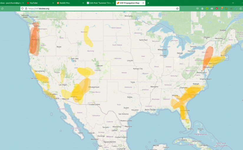
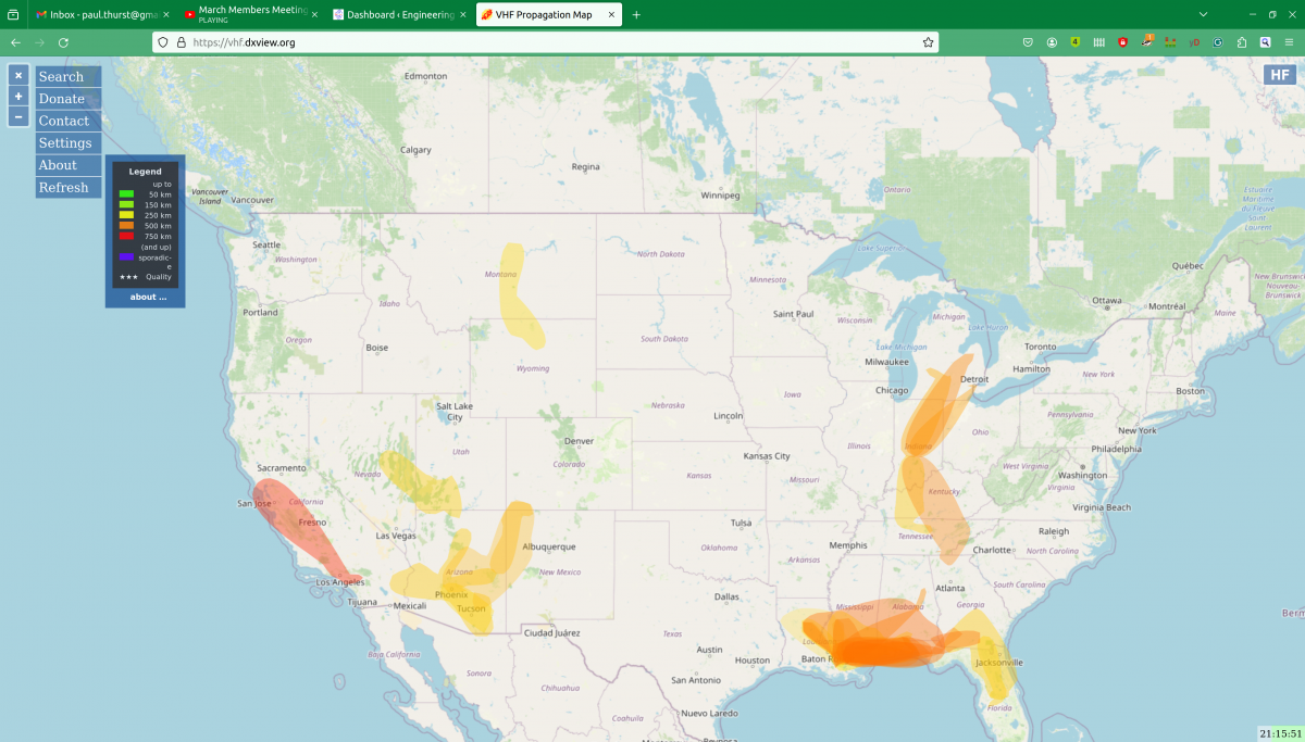
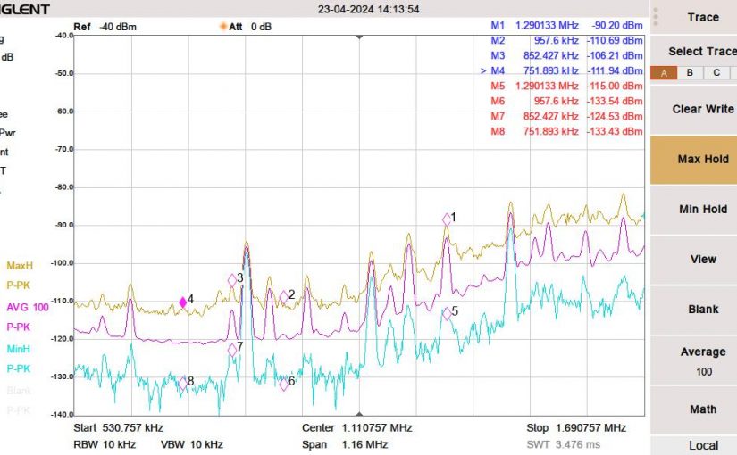
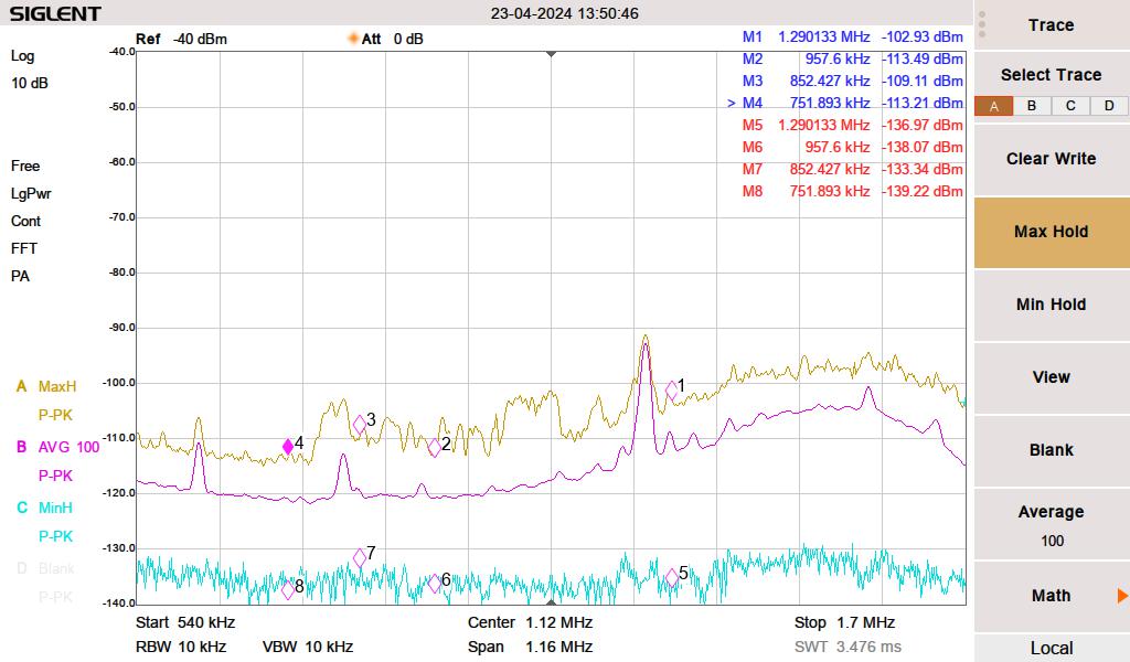
The yellow line is the peak hold, the magenta line is the 100 sweep average and the cyan line is the minimum peak hold. I live out in the sticks; there are no streetlights, no stoplights for miles, the nearest cellphone site is four miles away, and houses are spaced far apart.
First, I measured the noise with everything turned off. I then turned things on one by one, noting any changes in the spectrum. For the list noted above, this is the way it looked.
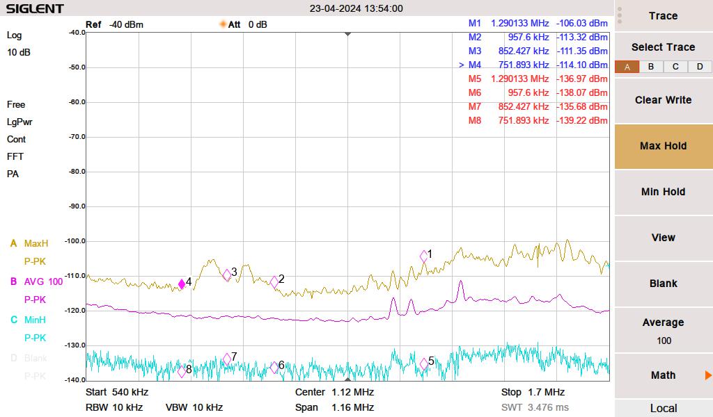
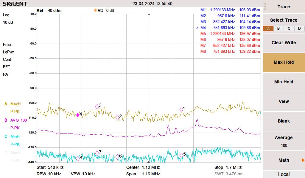
These are a few things contributing to RF noise levels on the MF band.
We have cheap Chinese grow lights to start seedlings for our vegetable garden. We were using these during the daytime hours to augment the low sunlight in early spring. I initially thought this was coming from the solar system. The interference was making a massive noise hump between 750 and 957 KHz. The brand of growlight is BestVA B-1000 LED which was purchased from Amazon.
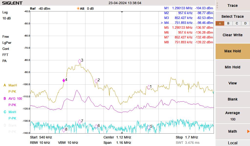
Next, somewhat surprisingly, the LG computer monitor on my desk was creating a pretty decent rise from 1120 KHz to 1700 KHz. I have three LG computer monitors, this is the newest only this one creates any RF noise.
Then, pretty much every florescent lamp (compact or full-length tube) created a broadband noise increase across the entire MF band and well into HF.
The vacuum cleaner makes a little bit of broadband RF noise when near the receiver. However, you cannot hear the radio when the vacuum is running, so that does not seem to matter.
None of these are surprising. However, I was more surprised that many other electronic devices are not contributing to RF noise in my house.
A little bit about data over power line or power line communications. Searching for power line data can be a bit tricky. First, there is this large voltage 60 Hz (plus harmonics) waveform to deal with. Secondly, there are many different protocols and many different frequencies. I narrowed down my solar system by listening to my Kenwood R-2000 below 300 KHz. Some noise went away when I completely disconnected the inverters. I don’t know the exact frequency, the protocol, the modulation type, etc. But there is something.
Data Over Power line is popular with home automation systems, it can be used to extend Ethernet LAN, and some power companies are using it to control substation equipment, smart power meters, and/or to function as an ISP for their customers. I have heard some HF users complain about BBPL, but I have not experienced it for myself.