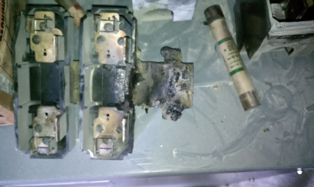
This picture reminded me of something that happened early on in my radio career:
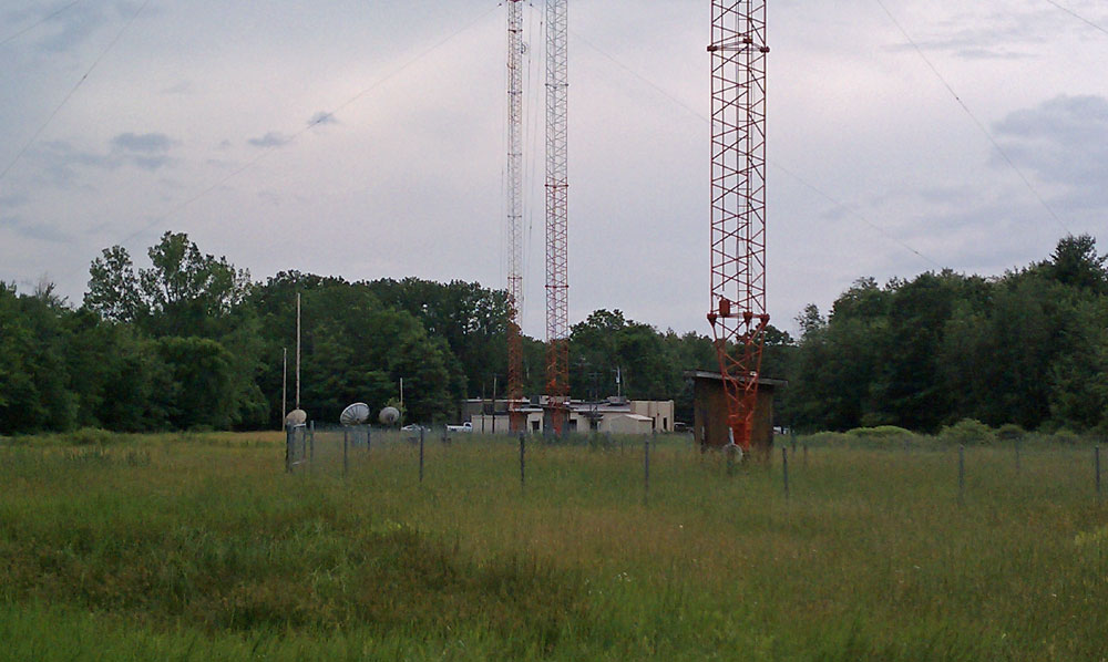
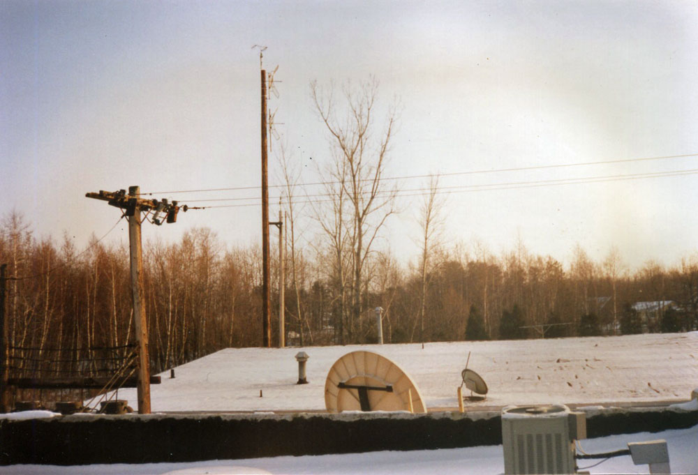
This is another view, looking across from the roof of the transmitter building before the former studio building was removed:
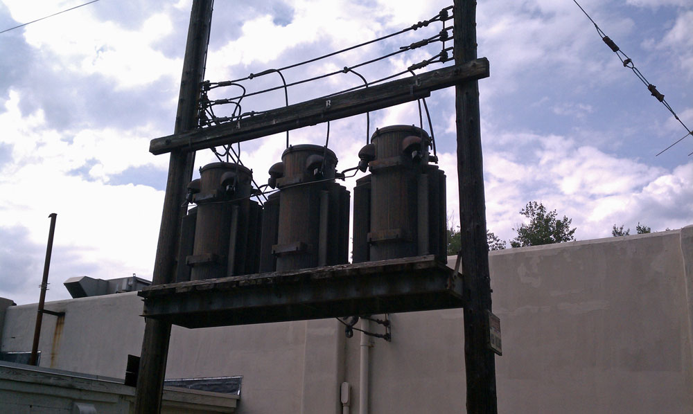
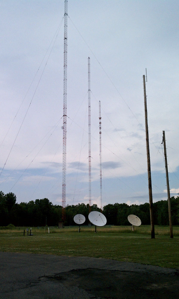
The story dates back to 1990 or so. In the second picture, one can see two Scala PR-950U Paraflector antennas. These are the STL and TSL antennas for WFLY. They are on wooden utility poles because of the WPTR 1540 KHz antenna system is behind the poles, out of the picture to the left. As you can see in the second picture, these poles were immediately behind the studio building, known as the “Gold Studio, ” the name itself being pure propaganda.
Also, in the second picture you can see behind the poles, a pair of poplar trees. The reason for the second, taller pole was because across the street, out of the picture to the right, there was a stand of poplar trees which were growing up into the path of the WFLY STL system.
When this was noticed, then General Manager, John Kelly, tactfully approached the property owner and asked if the radio station could cut the “popular” trees down. Of course, the property owner wanted much money to do this. There were many telephone calls and discussions on how to kill the “popular” trees and other, not-so-ethical solutions to this growing problem. Finally, it was decided that it would be simple and less expensive to install the taller utility pole.
Thus, Northeast Towers found the utility pole and came to install it. In this area of Albany, the soil is a sandy loam, which required many hands digging and back bracing in the hole before they placed the pole in the ground. As it is a seventy foot pole, a good 12 feet was placed in the ground and the hole was backfilled with concrete. That is why the pole still stands today.
Naturally, all of this work is taking place on the hottest day of the year. Also, it stands to reason, the guy in the hole doing the manual labor is the oldest, most out-of-shape person on the crew. After lots of grunting and swearing, our man comes out of the hole looking whiter than the driven snow and sweating profusely. He kind of staggered into the back door of the building and collapsed on the floor just inside the back door. At this point, he was in full cardiac arrest. The promotions director, whose office was closest to the door, called the ambulance.
Fortunately, the board operator on WPTR was an EMT with the local fire department. After his pager went off, he ran out to his car, got his EMT bag and arrived on scene within seconds. He was able to start CPR quickly. In the mean time, a crowd had gathered out in the hallway. John (the General Manager), hearing the commotion, storms out of his office and down the hallway. He gets to the edge of the crowd and yells:
“WHAT ARE YOU PEOPLE DOING HERE? DON’T YOU HAVE JOBS TO DO? AND WHAT IS THAT GUY DOING LAYING ON THE FLOOR?”
The good news is, the guy survived, thanks in no small part to the quick action of the board operator.
Anyway, tales of radio when it was fun.