UPDATE and bump: This post is from eleven years ago, but I have been working on an SDR project using one of the RTL- 2832 chips. I had to make two more of these units, so the prices and part numbers have been updated.
I have acquired one of those broad-banded software-defined radios, an Icom PCR-1000 to be precise, and all is well. I am enjoying listening to various MF, HF and VHF radio stations. However, there is a slight problem. Very slight, almost too small to even mention, more of an inconvenience than a problem. Still, if I am being inconvenienced, then others are too. This issue is with the antennas. My K9AY antenna works wonderfully from 500 KHz to 25 MHz or so. My discone antenna works wonderfully from about 30 MHz all the way up to about 1 GHz. In order to enjoy the full range of the receiver, I need to switch antennas. I have a small switch on my desktop, but it seems inconvenient to reach over and switch it when going from the AM band to the FM band or something similar. Therefore, I have decided that I need an HF/VHF receiver diplexer. One would think that such hardware is ready-made for such instances. However, nothing I could find commercially would do the trick.
Thus, since I could not buy one, I decided to build one to add to my collection of receiver doo-dads and nick knacks. The design is relatively easy, a back-to-back low pass/high pass filter system with a 50-ohm impedance throughout. Something with a sharp cut-off around 30 MHz or so:

Looks pretty good, 5th order Chebyshev filter, perhaps .1 dB ripple in the pass bands if well made. Schematically:

Then it comes down to the building. Since this is going to be used in the UHF range, care and attention needs to be paid to the layout of the components and the design of the circuit board. Some of those capacitance values are not standard, however, by using two capacitors in parallel, one can get pretty close. Since this is going to be used for receiving only, I may be splitting hairs, however, I have found that well-designed and built equipment is worth the extra effort.
The board layout looks like this:

I tried to keep the traces as close to 50 Ohm impedance as possible.
As one may be able to discern, C2 and C3 are in parallel to make 192 PF, C5 and C6 are in parallel to make 60 PF, and C7 and C8 are in parallel to make 163 PF.
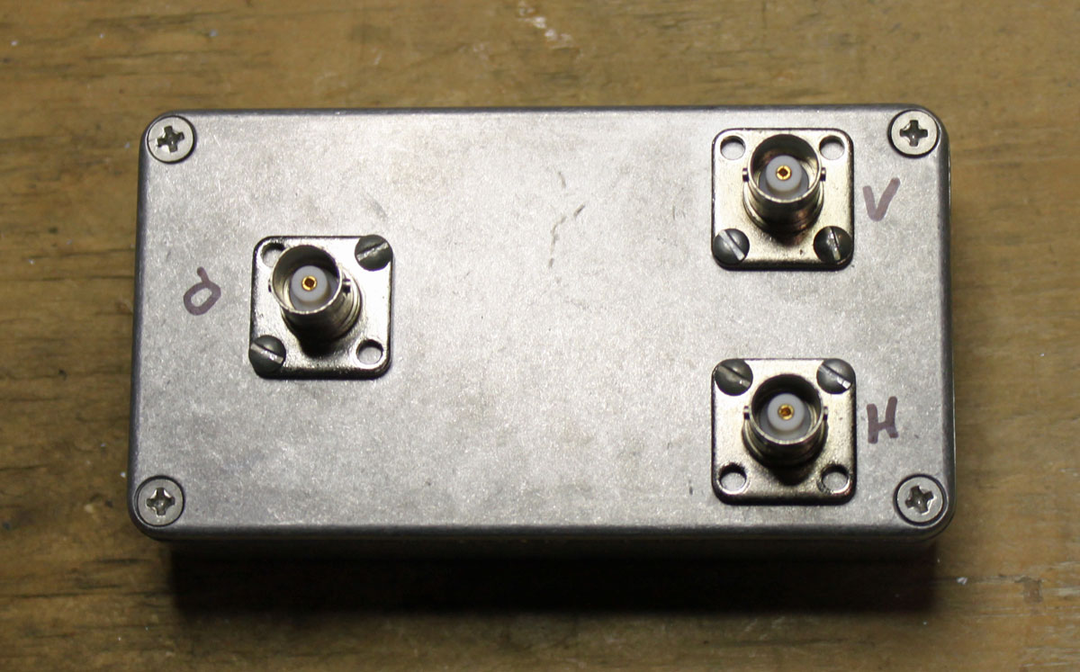
The input and output RF connectors are whatever the builder wants to use, however, I would recommend at least BNC or type N for the VHF/UHF side. My unit has all type BNC female connectors. Parts list:
| Nomenclature | Value | Mouser number | Cost (USD) |
| C1 | 150 PF SMT | 581-12065A151FAT2A | 0.72 |
| C2 | 12 PF SMT | 581-12061A120JAT2A | 0.26 |
| C3 | 180 PF SMT | 810-CGA5C4C0G2J181J | 0.27 |
| C4 | 68 PF SMT | 77-VJ1206A680FXACBC | 0.59 |
| C5 | 50 PF SMT | 581-12062A500KAT2A | 0.41 |
| C6 | 10 PF SMT | 80-C1206C100J2G | 0.54 |
| C7 | 3 PF SMT | 581-12061A3R0CAT2A | 0.34 |
| C8 | 160 PF SMT | 581-12065A161J | 0.34 |
| Case | Diecast, 4.3 x 2.3” | 546-1590WB | 10.71 |
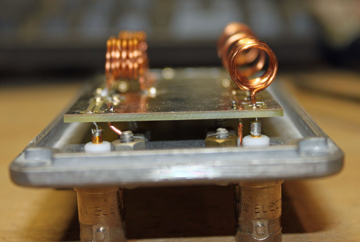
I chose a smallish, diecast aluminum case, which matches my other receiver gear. The circuit board noted above is 2.9 x 1.7 inches, which is a little bit small. I used 18 gauge wire between the input/output connectors and the board.
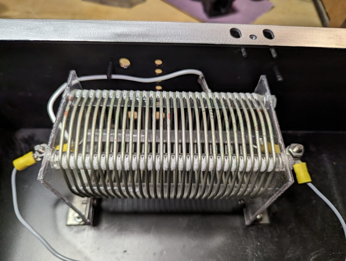
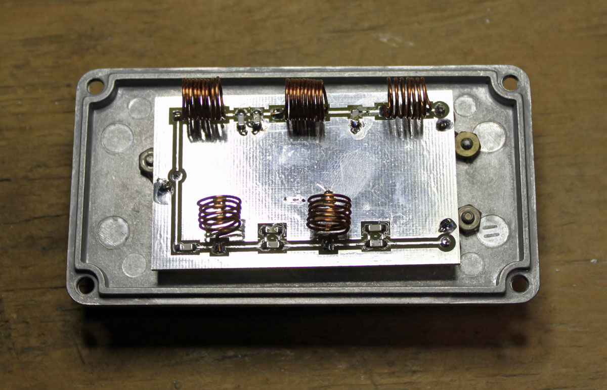
The inductors were made by hand. I used a small screwdriver as a winding form, making the turns tightly and then spreading them out to the proper distance.
Inductor chart:
| Inductor | Value (nH) | Diameter (mm) | Turns | Length (mm) |
| L1 | 173 | 8 | 6 | 9.5 |
| L2 | 468 | 8 | 10 | 9.8 |
| L3 | 414 | 8 | 9 | 8.7 |
| L4 | 146 | 8 | 5 | 7.2 |
| L5 | 186 | 8 | 6 | 8.6 |
The most expensive part was the circuit board, which cost about $16.00. The rest parts were about $22.00 including shipping.
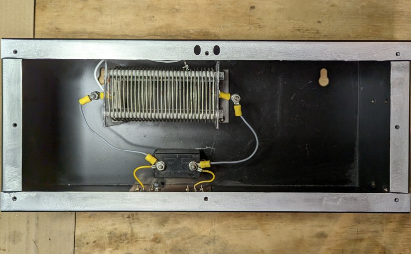
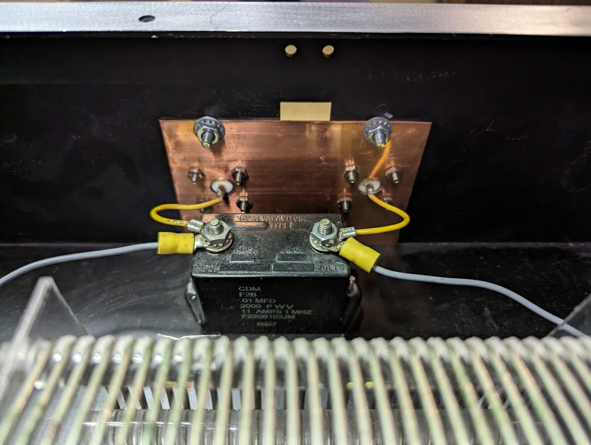
As built photos:
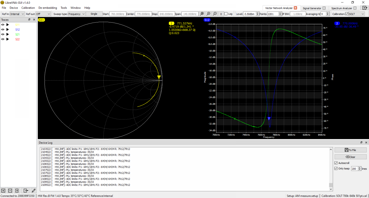
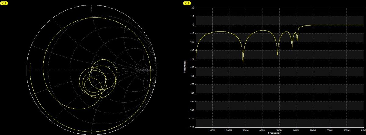
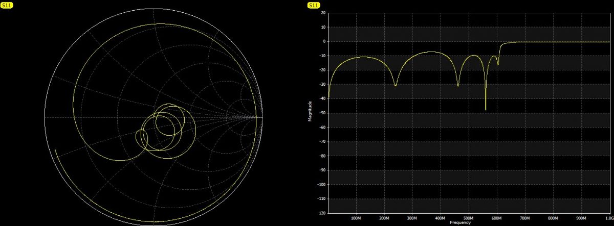
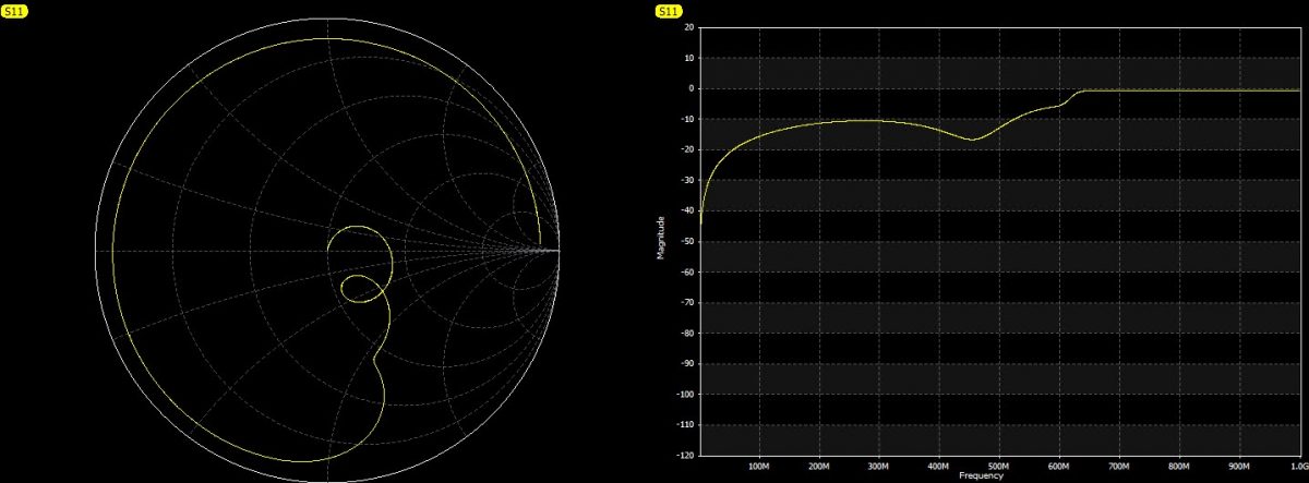
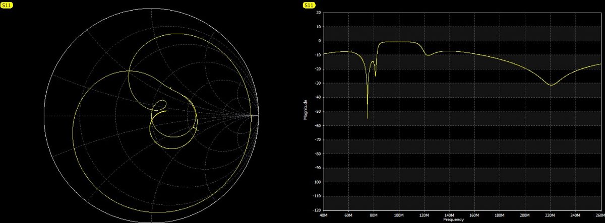
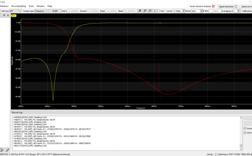
I have installed this already and it works great. I will need to get the spectrum analyzer out and run some signals through the various ports to see the attenuation and 3 dB roll-off points.