What the inside of a ceramic vacuum tube looks like

In case you have wondered it yourself:

4CX3500A
4CX3500A

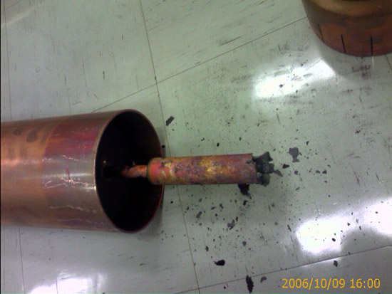
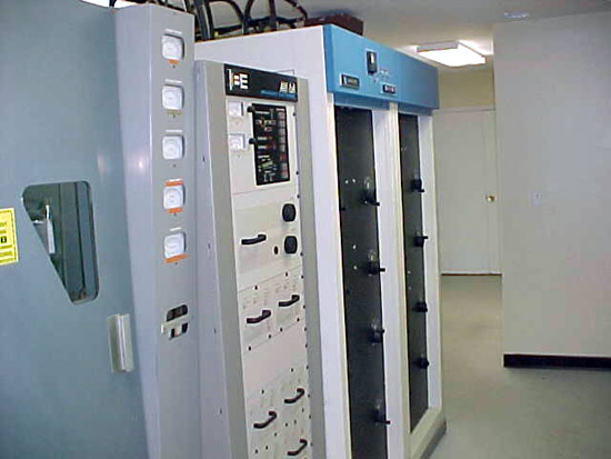
This is an EIMAC 4CX3500A which came out of a Harris HT5 transmitter. As you can see the ceramic cracked in half. When I arrived at the transmitter site, the unit was on full plate voltage, with no plate current, and no overload lights. I figured it might be something with the tube, so I tried to pull it out, but only the top half came. One of those “Ah ha” moments.

Fortunately, there was a working spare at the transmitter site and we got back on the air relatively quickly.  That, in and of itself is amazing considering the building that this transmitter lived in.  One of those abandoned former studio sites with the transmitter jammed into a back room somewhere.  To get to it, one has to dodge pigeons, beware of rats and wade through piles of garbage.

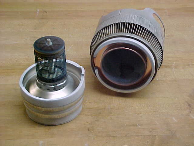
It is a little bit hard to tell in this photograph, but there are two “cages” which are the Screen and Grid.  The post in the center is the filament/cathode and the top detached part is the plate/anode.  In an FM transmitter, the exciter is coupled to the grid, and the screen accelerates electrons toward the plate and therefore controls the power, the plate collects the electrons and is coupled to the output stages and the antenna.  Good stuff.

BE AM6A power supply

Another picture from my collection, this one is the back side of a power supply module from a Broadcast Electronics AM6A transmitter:

Bang!
Bang!

It happened during power up from 1 KW to 5 KW and it was quite loud, as I was standing right next to the transmitter.  The exploded part is a 0.1 uf capacitor that looks like an add-on.  In fact, some of the other power supplies don’t have it.  It also took out the 20 amp slow blow fuse.

I like the exploded look of the board, kind of like on The Road Runner, when Wyle E. Coyote looks into a box and something explodes.

This is the only problem I have had with this particular transmitter.

Harmonic Filter for BE FM-30T

Another example from my blown-up shit collection, pictures archive:

Burned out harmonic filter, BE FM-30T transmitter
Burned-out harmonic filter, BE FM-30T transmitter

The harmonic filter from a Broadcast Electronics FM-30T.  This actually started in the bullet connector to the 3-inch hardline on the output side of the filter.

Burned out 3 inch hard line section
Burned out 3-inch hard-line section

Again, I did not install this myself, someone else did.  Cutting 3-inch hard line is pretty straightforward.  When using a field flange, the outer and inner conductors are cut flush.  Both conductors should be de-burred and filed smoothly.  It only takes a little thing to start an arc with 30 KW of FM power, so once again, attention to detail is key to avoiding these things.

Fortunately, BE sent along replacement parts for the harmonic filter and the line section was replaced.

AM transmitter site maintenance check list

As promised, here is the AM transmitter site maintenance checklist.  This is for a generic directional AM station with a backup transmitter, generator, and an RF STL.

Broadcast Electronics AM6A transmitter

Usual disclaimers apply.

AM site Maintenance checklist

Weekly Maintenance:

A.  Visit site, Check following:

  1. Check critical transmitter values against last logged value
  2. Check forward/reflected power on main transmitter
  3. Check and reset any overloads
  4. Check signal strength on STL against last logged value
  5. Check generator fuel level
  6. General check of building, look in all rooms, inspect for damage from vandalism, Leaking roofs, obvious signs of trouble, take steps to correct.

Monthly Maintenance:

B.  Visit site, Check following:

  1. Do a full multi-meter log, (includes tower phase angles, loop currents), run backup transmitter into dummy load.
  2. Start and run generator for 5 minutes, check block heater, hoses, belts, oil and antifreeze levels
  3. Calibrate remote control meters with transmitter meters, log it*
  4. Check all tower fences for integrity and locked gates*
  5. Complete Items 3, 4 and 5 under weekly maintenance.

Quarterly Maintenance:

C.  Visit site, Check following:

  1. Complete 1 through 5 under monthly maintenance.
  2. Check all air filters, clean or replace as needed.
  3. Check frequencies of all transmitters, STL receiver, and log.
  4. Complete quarterly tower lighting and painting inspection*

Bi-yearly Maintenance:

D.  Visit site, Check Following:

  1. Complete 1 through 5 under quarterly maintenance.
  2. Conduct monitor point readings for all directional antenna patterns*
  3. Check base current readings for day/night towers.  Ratio.*
  4. Clean backup transmitter
  5. Place backup transmitter on air and clean main transmitter.

Yearly Maintenance:

E.  Check all licenses and authorizations for accuracy. Make sure that all renewal cards etc are in public file and are posted at control point.*

F.  Visit site, Check following

  1. Complete 1 through 5 under Bi-yearly maintenance
  2. Equipment performance measurements (NRSC, Harmonics, frequency)*
  3. Complete service of generator
  4. Complete Inspection of towers, check for vertical and plumb, check guy wire tensions, retension as needed.
  5. Check property for anything out of the ordinary
  6. Repair driveway as needed

General maintenance that is completed on an as needed basis

  1. Re-fill fuel generator fuel tank when drops below 50 percent
  2. Empty trash, sweep floors, dust.
  3. Cut/remove vegetation inside tower fences, spray herbicide as needed
  4. Water proof tower fences every 2 years
  5. Paint exterior of building
  6. Replace tower lights*
  7. Paint towers*

*These are FCC inspection items, pay close attention if you do not want a fine.

That is it, a .pdf version of this file can be downloaded here.