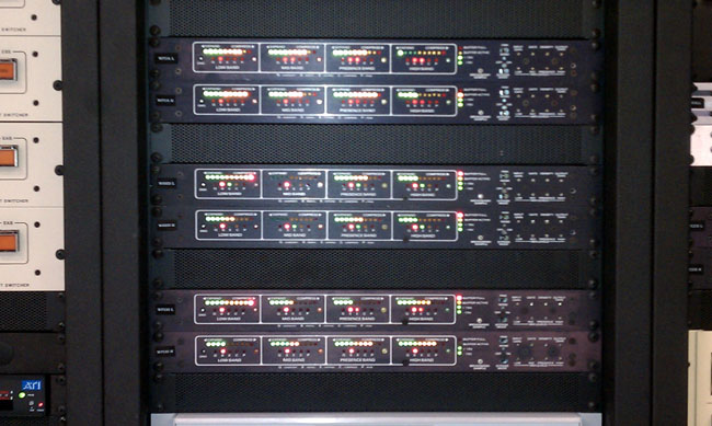
I love the sound of these units when coupled with an Optimod 8100A. Many people have (or rather, had) difficulty setting these things up. I found them to be very easy to deal with, just follow the instruction manual. If that doesn’t sound good, then there is something wrong with the unit. Over the years, there are only a few consistent problems. The first thing is with the voltage regulators. They have heat sinks attached with nylon screws. The screws get brittle and fall apart, making the regulator overheat and go bad. I have taken to replacing the nylon screws, and if the heat sink has fallen off, the entire regulator. There are also a few electrolytic capacitors in the power supply and on the audio board, it is always a good practice to replace those. Otherwise, unless the unit has been blown up by lightning, it should work.
As for set up, follow the directions in the manual:
Bypass the units using the bypass switch
Turn on the onboard pink noise generator
Using the test ports on the front of the unit, plug a Simpson 260 VOM set on 2.5 VAC important: use the ground port on the front of the unit, not the case
For use with an Optimod 8100A, using the dB scale on the Simpson 260, set all the bands for a 4.0 reading. Set the density to 3/4.
Turn off the pink noise generator and switch out of bypass mode.
Make sure the levels in the studio are where they should be.
Adjust the input gain so the “Buffer Active” light does not come on during normal-level programming.
Adjust the output levels so that the input buffer on the Optimod reads between -7 and -3 vu.
The rest of the settings are on the Optimod:
Clipping = 0
HF limiting = 5
Release time = 2
Bass coupling = 2
Gate = 0
Set the input attenuators for about 10 dB total gain reduction, with peaks around 15 dB or so.
Then set the L-R null. To do this, make sure the program material is in mono, then adjust the L or R input attenuator for minimum reading. Also, if the Audio Prism has PR-1 (phase rotators) installed, bypass the phase rotator in the Optimod. There is also a replacement card 5 made by Gentner called the RFC-1 for the Optimod 8100A. I notice little difference between a stock Optimod and an RFC-1 Optimod.
That is a good starting point. Most people are quite happy with this, but if needed, the high and low settings on the Prism can be adjusted slightly to suit the station equipment. When properly adjusted, this equipment rides gain, and adds a certain amount of loudness, while keeping the programming material natural sounding. Further, unlike some “modern” air chain processors, it does not boot up and it does not occasionally lose its mind, requiring a reboot.
The best paragraph in the manual, or any broadcast equipment manual is this:
There is a wealth of information available in the LED display. A few minutes of watching them in reduced light (emphasis added) while listening to a familiar program input will greatly help in understanding their action.
It will also greatly enhance your buzz, dude. It was the 70’s.
Could be. Digital Radio Mondiale, or DRM, is a modulation scheme that a group of broadcasters and transmitter manufacturers have been working on since about 1997 or so. There are numerous shortwave broadcasters; the BBC, the CBC, Deutsche Welle, Radio France Internationale, the VOA, and others have been using DRM on shortwave for several years now. I can state that the shortwave DRM system works well, I have a software decoder and use the sound card input on my computer to decode and listen to DRM shortwave broadcasts.
The goal of DRM is to establish a worldwide open standard for digital broadcasting in the LF, MF, HF, and VHF bands. In the early years of development, DRM was designed for digital broadcasting on bands below 30 MHz. This system is now known as DRM30. Since then, the DRM consortium has expanded that to the VHF band (up to 174 MHz) as well (meaning where the current FM band is located) and has called that system DRM+.
DRM uses COFDM (Coded Orthogonal Frequency Division Multiplex) modulation, which is the same as IBOC HD radioTM. This is a robust modulation system that employs multiple carriers at lower power (than an analog carrier) spread across the entire allotted bandwidth.
One of the claims is DRM transmits less power and is more energy efficient. In general, digital radio modulation does transmit less power, that is true. However, transmitters have to be run more linearly for digital due to the increased bandwidth. This may not translate to greatly increased efficiency from the AC mains to RF standpoint. Because of that, there is more waste heat, and thus more air conditioning is needed to cool the transmitter room.
Some of the advantages of DRM over Ibiquity’s HD radioTM are:
Open source system. Royalties are paid by the transmitter manufacturers only (and to date, most major US transmitter manufacturers have already paid these). There is no royalties paid by the broadcaster to install DRM or by the consumer when purchasing a DRM-capable receiver. One company does not own the rights to the modulation system for all the broadcasters in the country.
Universally standard; accepted by the European Telecommunications Standards Institute (ETSI), International Electrotechnical Committee (IEC), and the International Telecommunications Union (ITU).
The CODEC is HE-AAC 4, which is widely used worldwide.
DRM30 and DRM+ fit into existing band plans and will not interfere with other users on adjacent channels. DRM30 is designed for 9 KHz channel spacing and DRM+ is designed for 100 kHz channel spacing, all of which comply with existing FCC regulations.
Standardized receiver profiles are things that must be included in all DRM receivers. There are several advanced options as well, such as a media-rich system that includes video.
DRM+ has several added features: DRM text, which is similar to RBDS. EPG or electronic programming guide, which shows what is coming up next and a searchable schedule of when programs may be heard out to seven days. Some DRM+ receivers will have a TIVO-like recording device that allows the user to record programs and playback later.
Traffic reporting and routing
In addition to that, DRM30 stations have the ability to transmit low frame rate H. 264 video. This is a distinct advantage for short-wave stations that are seeking a way around firewall blocking. The video image is small, 176 x 144 pixels and it is 8 frames per second, which is about as good as can be expected using a 9 KHz channel.
In some cases, DRM is capable of a hybrid mode (ed note: DRM calls this “Simulcast mode”), but what have we learned about hybrid mode digital radio: It doesn’t work very well. In short, it would be better if DRM were employed in the digital-only mode. To many, this is a distinct disadvantage, but I don’t see it that way. There have been many that have made the IBOC rollout/FM broadcasting rollout analogy. Frankly, those arguments don’t hold water. When FM was introduced, no attempt was made to shoehorn it into the existing AM (Standard Broadcast) band, it was not designed to interfere with other stations or itself, power levels were sufficient for good reception using existing technology, quality over AM was markedly improved and programming was often separate (simulcasting with existing AMs did not start until later). My point here is that any digital broadcasting should be introduced on a separate set of frequencies. Some have proposed using TV channels 5 and 6, which makes some good sense. Whatever the outcome is, we have learned, the hard and expensive way, that hybrid digital broadcasting does not work well.
A brief video about DRM30.
Currently, DRM30 is only allowed on shortwave broadcast frequencies in the US. I asked a product development engineer from a major reputable broadcast transmitter manufacturer about this, and his response was:
Medium-wave broadcasting in the US already has HD radio, so the FCC would be disinclined to allow a new standard
One might be able to apply for an experimental license to broadcast DRM, but it would likely have an expiration date
It is possible to operate DRM in a hybrid mode on the AM band and occupy the same bandwidth as HD radioTM (30 kHz), it might also be possible to squeeze that down to 20 KHz.
Most modern (read: solid-state) AM broadcast transmitters should be able to transmit DRM without modification (antenna systems may be a different matter).
It might be fun to apply for an experimental license to broadcast somewhere in the 1600-1700 KHz range with DRM30 only and no analog modulation, except for an hourly station ID in Morse. A 1/4-wave tower in the middle of that band would be 141 feet tall. With the use of a skirt, a grounded tower can be employed. That and a few above-ground radials and the system would likely be pretty efficient. Part of the experiment would include driving around and taking signal strength readings while recording the programming material. This would give some real-world testing on how the system would perform in widespread use.
Of course, this would require a major about-face by the FCC, which is not likely unless someone there grows or somehow acquires a backbone.
Some people question the need to do any type of digital broadcasting. I am a realist, in one way, shape, or form, digital radio broadcasting will (or already is) take(ing) place. It would make the most sense if the best system were used, which is not necessarily the first system proposed. The big question is, will today’s terrestrial broadcasters be involved, or out of business?
Pictures and story sent along by occasional reader John. I worked on diplexing an AM station in 2003, it was a 5 KW and a 10 KW on a single tower. Those power levels require using some pretty large components, however, the setup was pretty straightforward. Each station had its own ATU (antenna tuning unit) which was then fed into bandpass filters to isolate the other station and coupled to the tower. The ATUs were set up as low-pass and high-pass filters respective to their frequency. The whole thing had something like 45 dB isolation, which worked(s) very well.
Doing this with a directional antenna system is another problem altogether. Add to that the tight filter networks required as the station are only 100 KHz apart. One saving grace, the power levels are relatively low. The higher the power gets, the more the magnetic fields build up around the coils and mutual coupling becomes an issue.
As John notes:
1560 (WGLB) owns the site and has been there for about 8 years. Originally WGLB was in Port Washington, WI with a BTA-250M running into a 2-tower array. The city of license was changed to Elm Grove, and this necessitated a move about 30 miles south to the site shown. A 6 tower combination array was needed to protect 1550 in Lake Geneva, WI, 1550 in Madison, WI, 1550 in Morris, IL, 1540 in Hartford, WI, 1570 in Appleton, WI, 1530 in Cambpellsport, WI and 1530 in Elmhurst, IL. A 4-tower in-line array is used on 1560 during daytime, and a 4-tower parallelogram with the two south towers switched in and the North two in-line towers switched out (floated) for 1560 nighttime operation.
WGLB WJTI combined directional antenna system
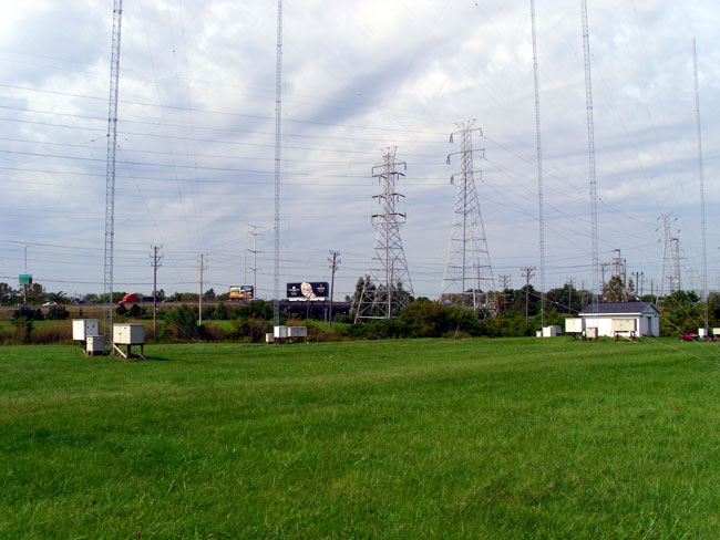
Looks interesting. Fortunately, the towers are not required to be painted or lighted, that is a big maintenance headache.
WGLB WJTI antenna field
Another thing to note; the site looks well maintained, the grass is mowed, no trees growing up by the transmitter building, the building is painted, etc. Likely these stations are locally owned and making a modest profit, not some abandoned afterthought.
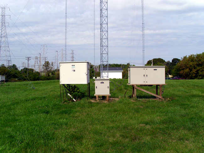
Antenna Tuning Units
Each tower has separate ATU’s for each station. The ATU’s then feed what is likely a very tight bandpass filter for each station, which then combines the two signals and feeds the tower. John continues:
An arrangement was designed when 1460 approached 1560 about leasing tower space for moving 1460 (ND-D) from Racine, WI north to West Allis, WI. This design is ingenious in that the array tower usage between the two stations is reversed for day-night operation! In other words, the 4-tower in-line array is used for 1460 nighttime, and the 4-tower parallelogram array consisting of the four south towers is used for 1460 daytime operation.
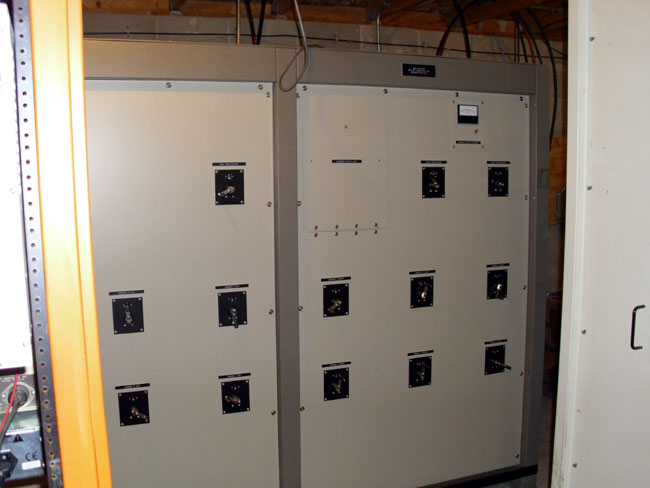
WJTI Phasetek antenna phasor
The 1460 pattern is pretty tight to protect 1470 at West Bend, WI approximately 30 miles north, and nighttime also to protect 1460 in DesMoines, IA. The friendly folks at Phasetek (Quakertown, PA) did the 1460 phasor and notch traps at each tower to prevent cross-modulation (inter-modulation) of the two signals feeding the towers, and after assembly on-site tuned up like a dream!
And that is saying something. I have dealt with phasor manufacturers before, sometimes they nail it, sometimes they don’t. Tune up can be a real challenge, which tends to put everyone on edge.
I might add that the high-tension electrical transmission towers nearby were de-tuned at 1560 years ago, and upon checking were broad enough to not require any further de-tuning at 1460! Another attribute of this design is that if something ever changes in the future, the deal can be easily be dissolved, because there is no mutual ownership of any equipment on site! It is truly one of the best “Win-Win” instances of AM station directional antenna combining I have ever seen!
It is good to see stations taking advantage of co-location these days. It is a great way to save money on real estate and hassles with the zoning boards, who all see dollar signs when someone talks of putting up a tower. With the amount of computing power and the lessons learned in the past 90 years or so, we are beginning to get this medium wave broadcasting thing down.
I found this in the great clean out of 2010, Bridgeport, Connecticut. Once upon a time, I had a slightly newer version of this, I think from 1972 or so. This version is from 1964 and gives a complete rundown of most small tubes that were manufactured back then.
There is something about a well-designed, well-maintained piece of tube gear. I remember an old Collins tube console that was in a production room at a small AM station. The console went dead (the paper clip shorted the B+) and I fixed it.
I recall listening to the test recording of my own voice from a reel-to-reel machine when I fixed the console. It sounded better than I’d ever heard it, not that I have a great radio voice, by any means.
A tube is a voltage amplifier versus a transistor, which is a current amplifier. A tube does not have the same fidelity as a transistor, as the voltage reaches its peak, it gets a little fuzzy, adding some distortion and harmonics. Tube gear adds warmth, what a musician might call Timbre. The combination of fundamental frequency and varying amplitudes of harmonic frequencies allow a listener to tell the difference between a piano and a guitar playing the same note.
This is what the current crop of tube mic preamps and other tube products tries to reproduce. Several companies have come out with an amplifier design that has mostly transistors and one tube, usually a 12AX7. Unfortunately, at least in my opinion, they fall a little short. If you want to have the “tube sound,” it needs to be all hollow state.
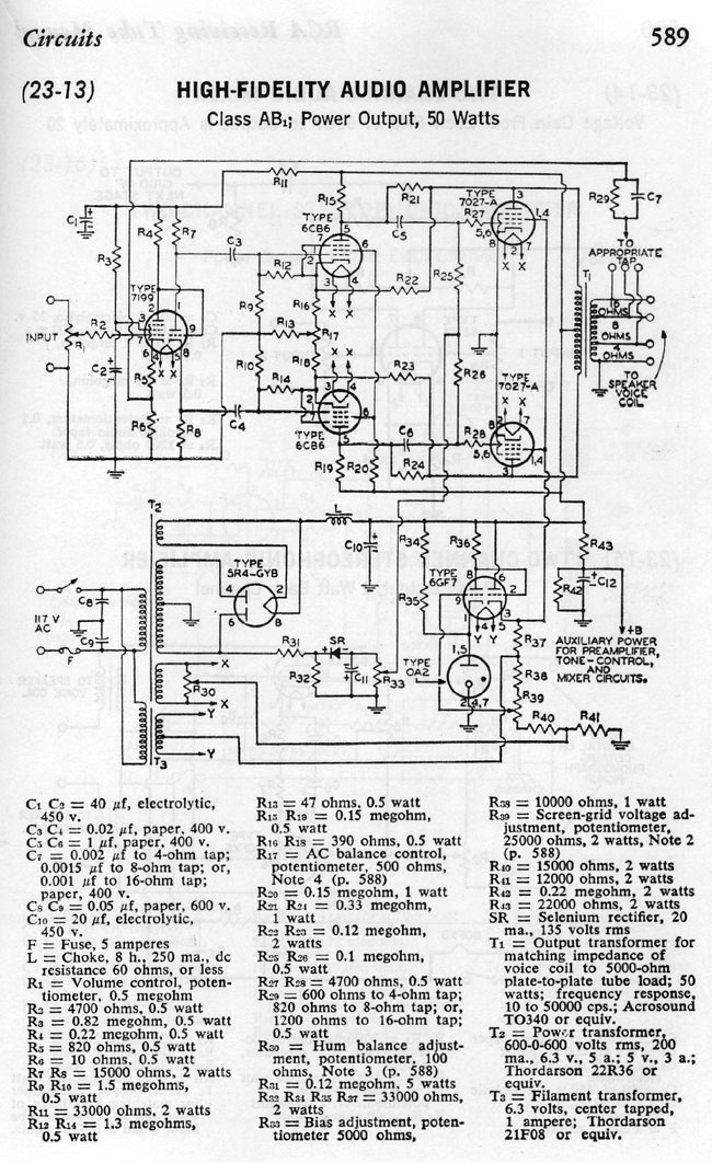
What is intriguing to me are the schematic diagrams in the back of the book. There is one for an audio amplifier:
RCA receiving tube manual audio amp schematic diagram, C 1964
This is a single-channel unit, for stereo, it would need to be duplicated. Also, I would lose the tube rectifier in favor of a solid-state full wave bridge, which would simplify T2 somewhat. The OA2 could also be changed to a diode. Looks like unbalanced audio, which could be modified with an input transformer.
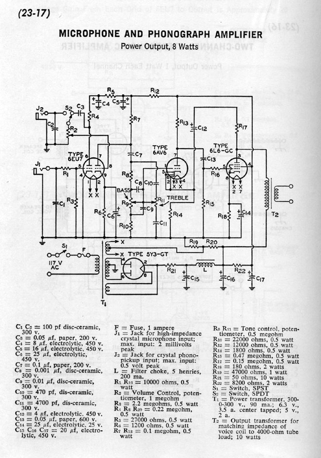
Another interesting diagram is this one, which can be used as a mic preamp:
Microphone Preamp schematic diagram RCA receiving tube manual C 196
That looks like a pretty solid design, a few tweaks here or there to add some gain reduction and some type of output level adjustment and I would be a really cool piece of gear. Again, the tube rectifier could be replaced with something solid state. The output transformer would likely have to be changed to something like 600 ohms.
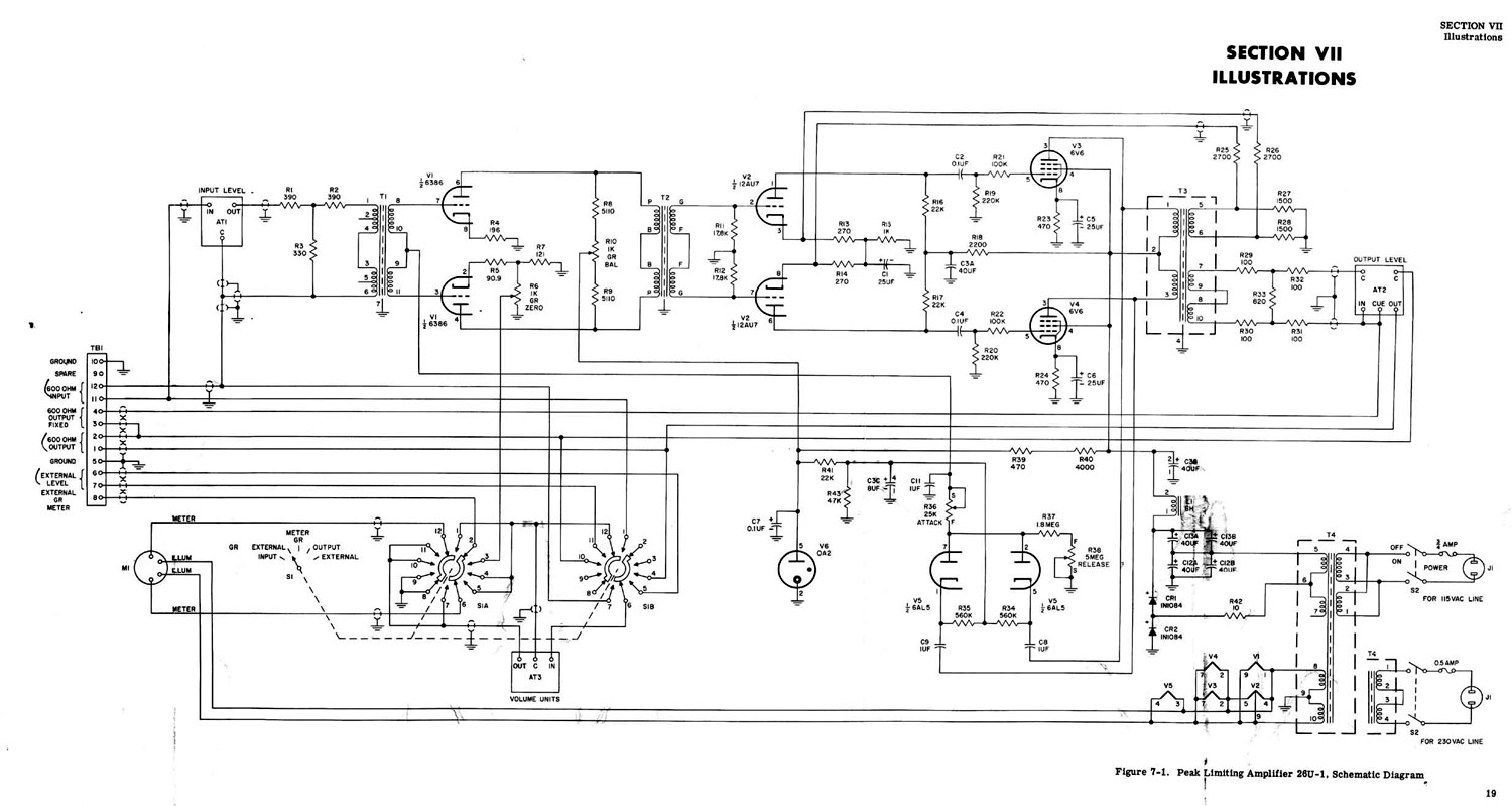
Couple that to something like this, the Collins 26U compressor/limiter, and one would have a great sounding microphone processor:
Collins 26U compressor limiter
Looks pretty cool. R10 is used to balance the two plate currents. I would be interested in the transformer values, input/output impedances, voltages, etc. The 6386 tube is very hard to find these days, a good substitute would be a 5670 which is still made by several manufacturers.
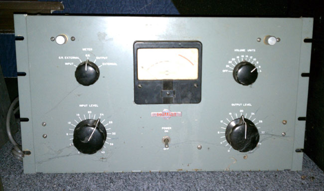
Update: This is a picture of a Collins 26-U sitting on my boss’s floor.