For those of you who are interested in radio listening, particularly over long distances (AKA DXing) with even a moderately directional antenna, having a great circle map projection for your location is a necessity. Looking at a Mercator Projection, the normal “flat” map most are familiar with, one might come to the conclusion that due west from upstate NY lies the Washington/Oregon state border. Appearances can be deceptive, bearing away at 270 degrees true (due west) from upstate NY is the California/Mexico border.
This is because we live in a big sphere. In this regard, the only place the Mercator Projection is accurate is around the equator unless one is going due north (0 degrees) or due south (180 degrees). The further north or south from the equator, the less accurate a flat map is. Therefore, having a Great Circle map projection based on your location is handy for choosing the right azimuth to listen along.
As with many things, the internet provides the required tools to generate a great circle map for any location in the world. The first thing needed is an accurate fix of your location. This can be obtained via GPS, or, if you know how to look at a map and or satellite picture, itouchmap can be very useful. Once you know where you are, you can plug that information into this Great Circle Map Generator.
I saved the image as a bit map and used it as the wallpaper on my computer. That way, I just need to minimize any running programs and I can see what the correct azimuth is to any place in the world. This is for upstate NY:
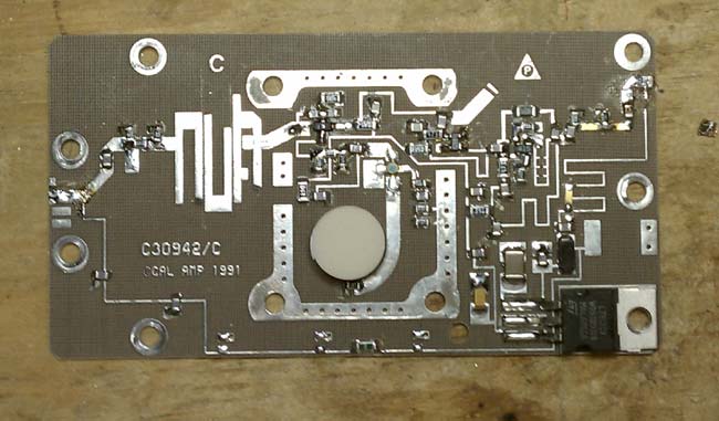
A quick glance at almost any circuit board these days will show that almost all of the components are surface-mounted. They are small rectangles or squares that sit on top of the circuit board. This is different from the through-hole components that were used for many years and are still found in older equipment. There are radio engineers who feel that surface mount components are too hard to work on, thus the boards are not repairable.
California Amplifiers C band block down converter
As with anything in the engineering field, there needs to be a cost/benefit analysis. Most computer component boards, things like NICs, modems, sound cards, VGA cards are very inexpensive, and often times it would be more expensive to repair the board than it would to buy a new one. In other situations, however, local repair of circuit boards makes good sense and can be a good learning tool.
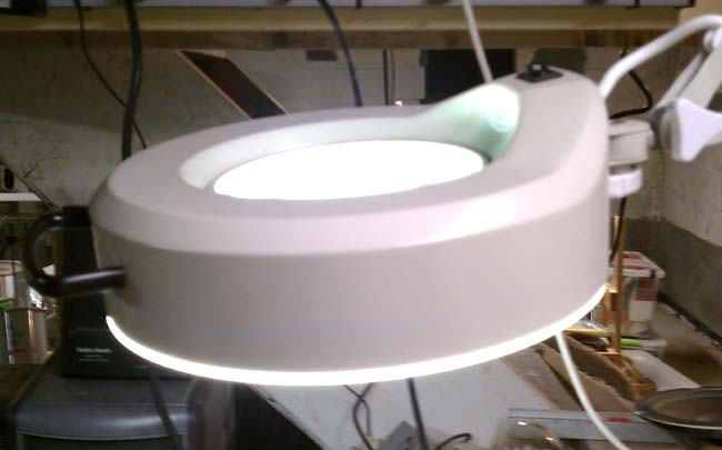
Consoles and transmitters offer some good opportunities for local repair, provided the schematics are available. SMT component troubleshooting is the same as through-hole troubleshoots, except the components are smaller. That is where a magnifying glass comes in handy. I purchased a magnifying glass/light to work on SMT boards.
three diopter magnifying lamp
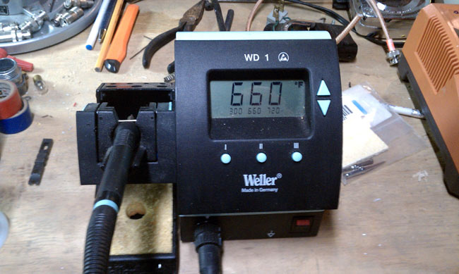
Soldering and unsoldering techniques are also different. A temperature controlled soldering iron with a small tip is important. I find the easiest way to unsolder a component is with solder wick. Once most of the solder has been wicked up, a brief touch of the iron and the component will come off. Small resistors and capacitors are fairly rugged, but should not be overheated. Semiconductor components such as diodes, transistors and ICs are susceptible to heat damage and Electro Static Discharge (EDS). A grounding wrist strap should always be used when handling semiconductor components. Soldering iron temperature should be enough to quickly melt the solder and heat the connection surface without overheating the SMT component. Lead free solder requires slightly higher temperatures than the traditional 60/40 rosin core.
Weller WD1 temperature-controlled soldering station
A temperature-controlled soldering station is a must. Too much heat will damage components and boards, too little will make soldering SMT an arduous task.
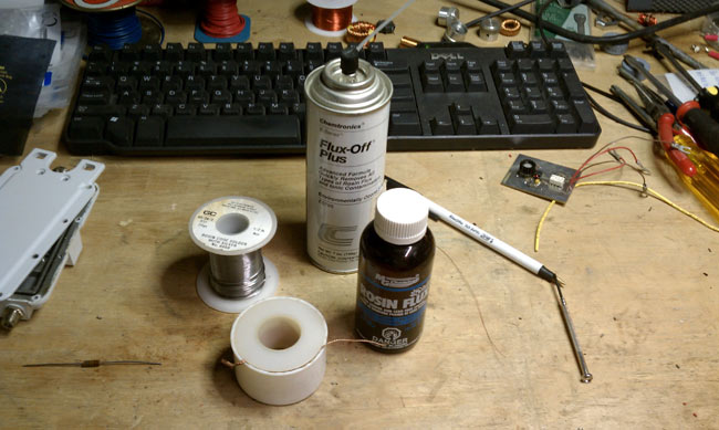
Soldering supplies
Other soldering supplies include liquid flux, desoldering wick, flux remover and 55/40/5 solder. The desoldering wick makes it easy to clean up an errant solder deposits and is the best way to desolder surface mount components. I have had limited success using a solder pump on surface mount boards. They do come in handy for RF MOSFETS, which have large tabs, often with liberal amounts of solder applied at the factory.
Soldering new components:
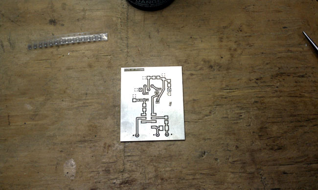
HF receiver preamp SMT board
A typical 0.1 uf capacitor is placed on the surface mount board and ready to be soldered. These components are all small, but I would characterize this as a medium sized one. There are some very small diodes, ICs and other devices that require the magnifying glass to identify pins and polarity.
The best way that I have found to solder components onto a surface mount board is to use a little bit of liquid flux on the board.
Using tweezers or small needle nose pliers, place the component.
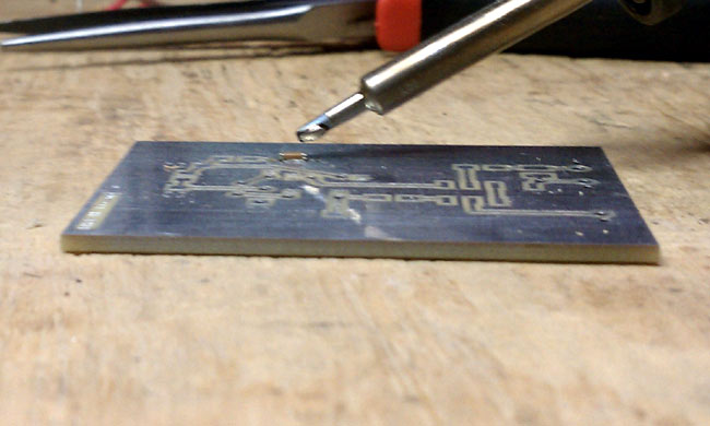
Soldering 0.1 uf bypass cap on SMT board
Wet the end of the soldering iron with a little bit of solder.
Using the placing tool, hold the component in place and touch one of the pads with the soldering iron. This should tack the component in place. Solder the component to the other pad using the soldering iron and solder. Then come back and touch up the tacked side. I have found that 600 degrees F is a good temperature to quickly melt the solder, while not heating up the component too much.
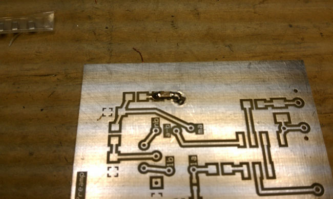
HF receiver preamp with bypass capacitor soldered
Sorry I could not get pictures of the actually process, I don’t have enough hands to hold the soldering iron, hold the component down and take a picture.
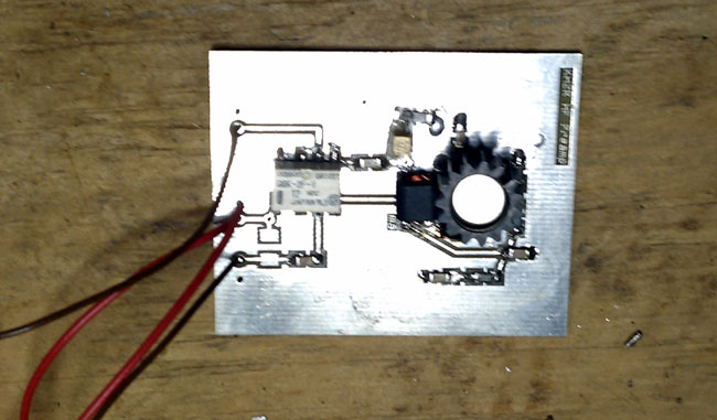
HF preamp based on Norton 1N5109 design
The completed preamplifier. I have been calling this an HF preamp, because that is its intended use. In practice, this preamp should work well from 50 KHz up to about 75 MHz, with 3dB points at 30 KHz and 100 MHz.
Norton HF preamp Schematic
The Norton design is an inverse feed back and using the 1N5109 transistor, which has input and output impedance of 50 ohms, makes it simple to implement. In testing, I found this unit has about 10-11 dB of gain with about 4 dB of noise. The use of SMT makes the design stable and I didn’t see any evidence of oscillations when testing it. More on the preamp here. I installed it out at the base of my K9AY antenna and it can be remotely turned on and off as needed. My main reason for wanting it is to overcome the 6.5 dB signal loss in the four port hybrid receiver coupler and transmission line I use. Truth be told, most of the time it is off.
The WICC transmitter site, Pleasure Beach in Bridgeport, has been cut off from normal access since the bridge to the island burned in 1996. Since that time, access has been by boat with a 0.93-mile walk from the dock to the transmitter building.
Last summer, LVI Construction, under contract from the Town of Stratford, put in a temporary road and began removing the burned out cottages. While that road is in place, the radio station has been able to access the site and get many important things accomplished. These include:
Removing several decades worth of stored crap, garbage, obsolete and unused equipment
Repair the electrical service to the building
Replace the generator transfer switch
Repair the Sonitrol building alarm
Replace the old Onan Generator
Have the power company replace the 3-phase circuit from the point where the underwater cables come ashore to the transmitter building.
All of these projects should greatly improve the reliability of the station. This should make Bill, happy, who appears to have a WICC chip implanted in his brain because every time the carrier is interrupted he posts about it on the radio-info.com website.
The biggest issue with the site was the utility feed from the shore to the transmitter building. The original circuit was installed in 1936 when the station moved to the island. It was old and the poles were all rotting and had horizontal cross arms. Ospreys especially liked the horizontal cross arms as they made good nesting spots. That is, until the nest shorts out one of the phases catches on fire and burns the top of the pole off. This has happened several times over the years causing many hours of off-air time.
WICC new utility service
United Illuminating, the local utility company, was very cooperative and installed new utility poles, wires, breakers, and transformers, this time with a vertical phase arrangement, which should keep the Ospreys off of them. Additionally, the cottage removal project included installing Osprey nesting poles.
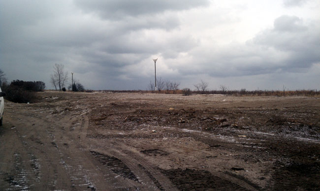
Pleasure beach cottages removed
With almost all of the cottages now removed, the area looks much better than before. Actually, it should be a nice nature preserve, and hopefully, the absence of the buildings might reduce the number of vandals in the area. The work is almost done, so the road is about to be taken up. This means we need to wrap up the work out there, so the final push is on.
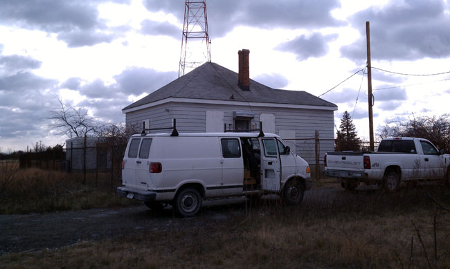
WICC transmitter building
In the last three weeks, 10 truckloads of junk have been hauled out of the transmitter building and generator shack. Over 1,500 pounds of scrap steel, 640 pounds of insulated wire, 2,000 pounds of particle board furniture, old t-shirts, and hats (something called “Taste of Bridgeport” which, if anyone knows what that was let me know), old propane tanks, batteries, etc. We also managed to fix the fence and gate in front of the building and cut down the overgrown yew bushes and bittersweet vines.
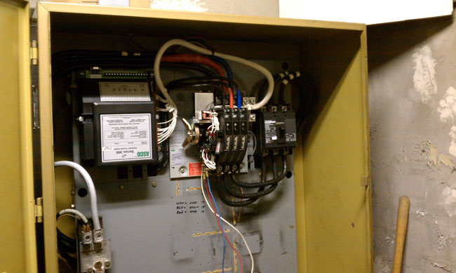
Transfer Switch
The old Kolher transfer switch was also an issue. There was no place to mount a new switch inside and mounting one outside is out of the question, so the guts from the Kohler switch were removed and replaced with an ASCO unit. This was done in the summer of 2009. The breaker on the right side is the main service disconnect for the building, which was installed in September.
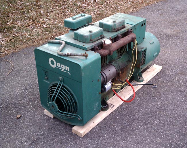
Onan 12 KW 12JC 4R air cooled generator, removed from service
Today, it was time to replace the Onan propane generator. The old generator is an Onan 12JC-4R air-cooled propane unit which was installed on April 4, 1969, at a cost of $1,545.00. For many years, this unit gave reliable service, but it has many, many hours on it and it lacks the fault/self-control circuits needed for remote (read desolate) operation. Several times over the last few years, the generator would run out of gas or the propane tank would freeze up and the starter would crank until it burned out.
It was cold out on the island, with temperatures in the twenties and a bitter west wind blowing right into the generator shack. All of this conspired to make working conditions difficult. Wind chill readings were in the single digits all day long, and in spite of long johns and extra layers, by 3 pm I was shivering and even several hours after coming inside, I still felt cold.
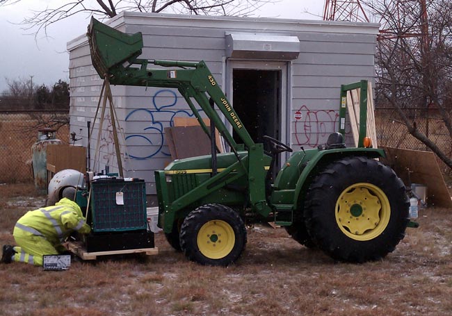
Using tractor to move new generator
The new generator is a Cummins/Onan 20GGMA which is rated for 20 KW. We used a John Deere bucket tractor to move the generator from the flatbed truck to the generator building, and then push it inside. The old generator wiring to the transfer switch was reused, but a piece of flex was used to connect to the generator instead of the solid conduit. The building fan was also wired up so that it would run whenever the generator was running.
The generator load with all possible things switched on and the transmitter running at full power is about 12,000 watts, but this would mean the air conditioner and tower lights were on during the daytime. More likely, the transmitter will be at low power when the tower lights are on and the AC will be intermittent on/off at night. At full load, this generator uses slightly less than 2 gallons of propane per hour. At half load, I’d estimate that to be 1.4 or so gallons.
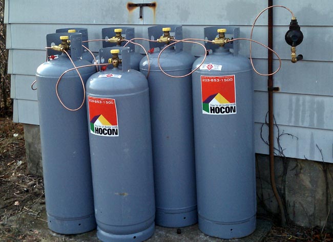
Cummins Onan generator in new home100 pound propane gas tanks
HOCON gas came out and connected six 100-pound propane tanks in series, which should prevent tank icing. Propane weighs about 4.11 pounds per gallon, therefore the fuel supply should last about 100 hours, or 4.5 days, give or take. Why 100-pound tanks? Because we will have to shuffle them back and forth between the dock and the generator shed, a journey of about one mile, in a cart. Anything larger would be impossible to deal with. Even so, refilling the propane will be a 2 person job and will likely take all day.
Shortwave broadcasting is often overlooked as a domestic news outlet. This is by design and is a throwback to the Cold War era when shortwave broadcasting was seen as an international propagation outlet, mainly used by the VOA. In fact, according to the Smith-Mundt Act of 1948, the Voice of America is forbidden to broadcast directly to American citizens. The intent of the legislation is to protect the American public from propaganda actions by its own government. Nice, huh?
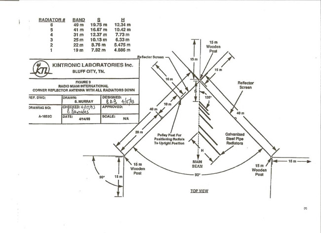
WRMI corner reflector
The way the FCC rules governing shortwave (AKA HF) broadcasting are written, the station needs to be designed and configured to transmit signals to areas outside of the US. Any coverage within the US is considered incidental. See also CFR 47 73 part F.
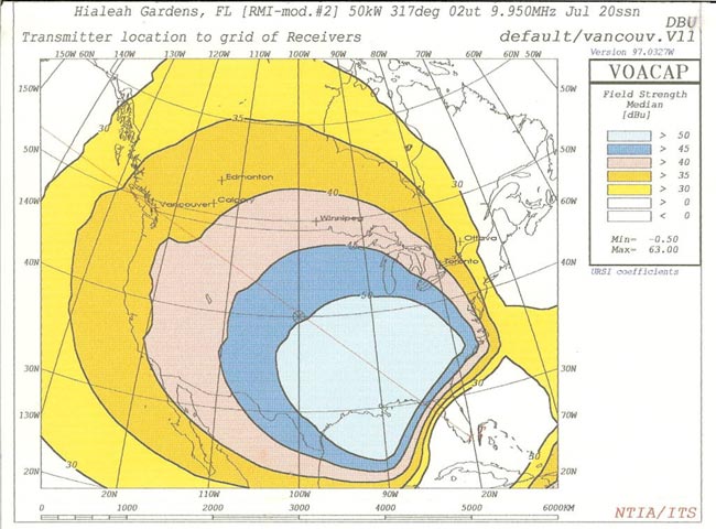
WRMI signal 50 KW 9950 KHz
That being said, many of the non-VOA HF broadcasters are well-received in the US. There is nothing that is preventing a shortwave station on the west coast from beaming its signal across the North American continent to Europe, or over the poles, etc. These stations’ call signs start with a K or W much the same as FM and AM broadcasting stations. Most of them are religious broadcasters, however, there are a few that offer non-religious programming or a mixture of both.
As Clear Channel lays off more staff and becomes a computer-automated shell, I am beginning to think that traditional AM and FM broadcasting is on the way out. Television news and the 24-hour news cycle have blurred the line between journalism and opinion. Newspapers have filled the role of government watchdogs and general information sources since this country was founded. Newspapers have fallen on hard times with many cutting investigative reporters, general reporters and or going out of business. The internet has become the de facto information source for many people, which is fine so long as users understand its limits.
The big problem with all of this is the internet is a fragile thing, controlled by a few very large companies. A few keystrokes and a router table are re-written to exclude a site that might have detrimental information. Distributed Denial of Service attacks have taken down Wikileaks for days. Collateral Wikileaks-related damage occurred to Amazon.com, Visa, Mastercard and Paypal. A few “persuasive” calls from an important government agency or official to an ISP or server company can easily take a site or multiple sites offline. Search results can be skewed by search engines, or by large companies like BP did during the Gulf oil spill.
The FCC debates on so-called “net neutrality” have yet to produce any meaningful framework to avoid corporate and search engine censorship. This also assumes that the government can justly regulate the internet, which, in this day and age is a stretch of the imagination.
All of this is leaving an information void. As the saying goes, nature abhors a vacuum.
Enter Shortwave Radio. Now, I’ll be the first to admit, there are a lot of strange things that can be heard in the shortwave broadcast band. However, it one can separate the wheat from the chaff, some rewarding entertainment can be had. Most of the non-government shortwave stations in the US are religious broadcasters. There are at least three stations that offer time-brokered programs, some religious and some not. WBCQ is always a good bet. WRMI is offering more and more non-religious programming. WWCR also has some general programming. While government broadcasters like the BBC, CBC, and others have greatly curtailed their broadcasts to North America, this is not necessarily a bad thing, as other smaller broadcasters can be heard where the giants once roamed.
As solar cycle 24 heats up, the programming selections on any given day can vary widely. Radio Australia (ABC) has been booming in on 6020 KHz in the mornings around here. They have an excellent country music program and I have been introduced to several songs and musicians that I would not have otherwise heard. Today I heard a great show on Radio Australia Today about New Orleans, Ray Nagin, the aftermath of Hurricane Katrina, and lots of things that aren’t normally heard here in the US.
The key to shortwave listening is the receive antenna. One particular MF/HF receive antenna is the K9AY loop. I have had very good luck with that antenna on both standard and international broadcasts. I have to say, I am finding fewer and fewer things to listen to on the AM band. I have taken the opportunity to make a few circuit boards with a 10-12 dB preamp for controlling the pair of loops used in a K9AY array. The preamp is based on a common base Norton design, which has low noise and moderate gain. I use the preamp sparingly, the main reason for it is the 4 way hybrid splitter, which adds 6.2 dB of loss to the antenna output. Still, I have noticed, especially on narrow bandwidth digital signals, that the preamp can mean the difference between decoding a signal or not.
I am making extras, K9AY antenna systems, preamps, receiver splitters, and other general shortwave receive systems, which I plan to offer for sale at a later date. As they say, stay tuned.