Satellite dishes have been a part of radio station technical equipment for years. I am surprised at the number of broadcast engineers that do not consider center of box when aiming dishes. As dishes get larger and focal points get smaller, center of box aiming is not a nice thing to do, it is a necessary thing to do. The latest generation of satellite receivers, (AKA XDS) have a somewhat less than lively RF front end, they require higher E/B than the previous generation Starguide receivers to stay locked.
For years, the majority of commercial radio networks were carried on AMC-8 or its predecessors living at 139° W. On the East Coast, particularly in the Northeast, that makes aiming points relatively low to the horizon, anywhere between 8-10° elevation.
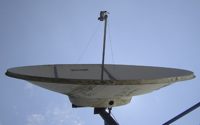
3.2 meter COMTECH satellite dish
This all means that precise aiming the satellite receive dish is critical for satisfactory performance. SES Americom owns AMC-8 and thus they have a web page about all of their satellites and important operating information. SES Center of box for AMC-8 is available in one-month blocks, which makes scheduling the aiming chore fairly easy.
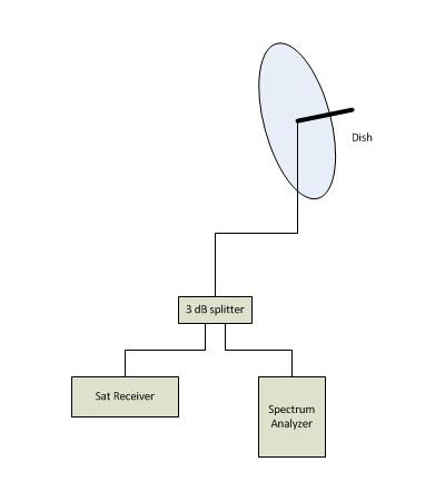
Large satellite dish aiming diagram
I have always used a spectrum analyzer through a 3 dB splitter to look at the 950 MHz LNB output. This aiming setup allows the best combination of Azimuth/Elevation/polarization. Using the satellite receiver to confirm and maintain signal lock, peak the waveform that the receiver is locked to. It is pretty crowded up there, so there will be lots of signals on the spectrum analyzer trace.
It is a pain in the rear end to lug all that equipment out to the satellite dish, especially if it is on the roof. That is why it only need be done once; the right way the first time.
Any shortcuts will likely lead to those annoying chirps and dropouts or complete loss programming, particularly when the weather turns bad.
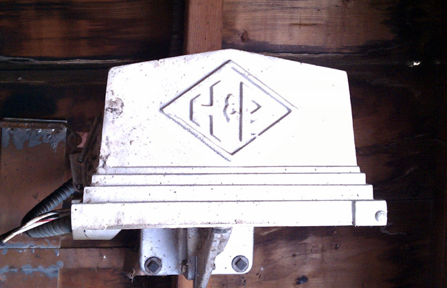
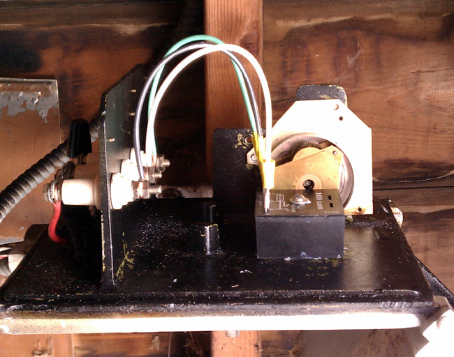
This is a Hughey Phillips mechanical tower light flasher that has been in service since 1960. Basically, it is a motor connected to a cam that rocks a mercury relay back and forth. These were standard technology for tower lights from the 1930s through about 1970 or a little later. They were very reliable, we still have some with a “pancake motor” in use on some of our towers. They were very robust and immune to lightning damage, RF interference, and other problems. The only maintenance that I can think of is lubricating the motor bearings. Eventually, however, they do wear out. Cold weather seems to take its toll, often causing the motor to stop.
Hughey and Phillips mechanical tower light flasher
This particular unit is mounted inside the tuning house for the far tower (north tower) at the WGHQ antenna array. It has finally reached the end of it’s existence; the motor bearings are shot and it has gotten stuck in both the on and off position this year causing the FAA to be notified of the malfunction.
WGHQ 920 Khz Kingston, NY antenna array
Today, I am replacing it with a solid-state flasher (SSAC B-KON FS155-30RF). Solid-state flasher units have been known to malfunction in high RF fields, such as AM towers. To cure that, the manufacturer has built-in 0.01 uf bypass capacitors, hence the “RF” suffix. Older units did not have built-in bypass caps, so external 0.1 uf bypass capacitors were normally installed on units mounted to AM towers. While I was working on this, I turned the transmitter down to 500 watts, no need to get any RF burns.
Naturally, this has to happen after there is two feet of snow on the ground. Also, it should be noted that this is the furthest tower away from the transmitter building. Now where did I put those snow shoes? Never mind, it has been very cold and the ground is frozen solid, I’ll take the truck… This is good because I will have all the tools, drills, nuts, and bolts without having to walk back and forth several times in the snow.
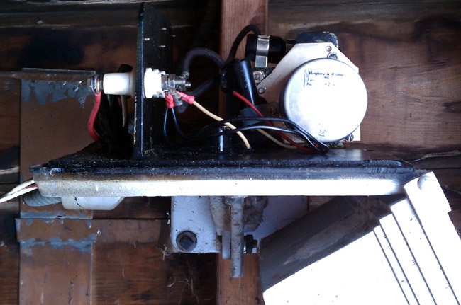
Hughey Phillips mechanical beacon flasher
I removed the motor and mercury-filled relay. I’ll have to figure out how to dispose of the relay. I then drilled a mounting hole through the base of the old flasher housing and bolted the solid-state relay to it. This is required because the solid-state relay needs a pretty good heat sink.
SSAC B-KON tower light flasher
Turn everything back on and: Ta-da! All works normally, the tower beacon is flashing away up there. Time to leave.
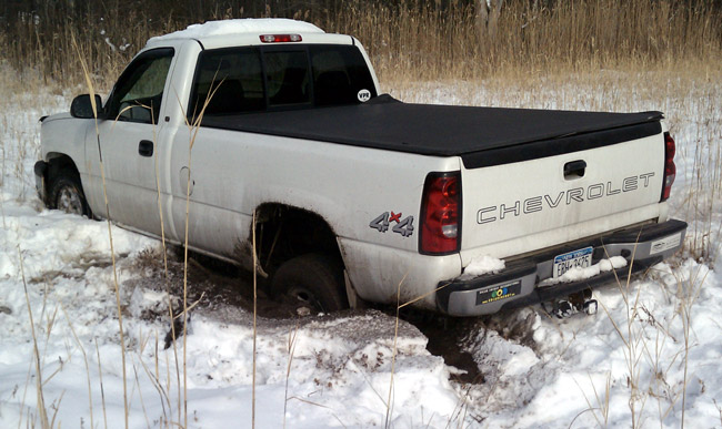
Truck stuck in swamp
Pull forward about 2 feet to turn around and CRUNCH! The truck goes through the ice of a hidden stream. Any attempt to move only makes it worse:
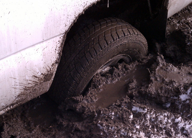
Truck rear burried to axle
Put in a phone call to the one guy I know that can get me out. About an hour later he shows up with chains, a shovel, and a come-a-long. We attach the come-a-long to the fence support post and pull the truck out backward 1/2 inch at a time. It took us about an hour and a half to get it all the way out so I could drive it back across the field. I’d have taken some pictures, but my guy; was a little grumpy.
I won’t do that again.
Still, I did the job I came to do, so it was a good day after all.
IP networks are the largest standardized data transfer networks worldwide. These networks can be found in almost every business and home and are used for file transfer, storage, printing, etc. The Internet Protocol over Ethernet (802.x) networks is widely understood and supported. It is robust, inexpensive, well-documented, readily deployed, and nearly universal. Many equipment manufacturers such as Comrex, Telos, and Wheatstone have developed audio equipment that uses IP networks to transfer and route audio within and between facilities.
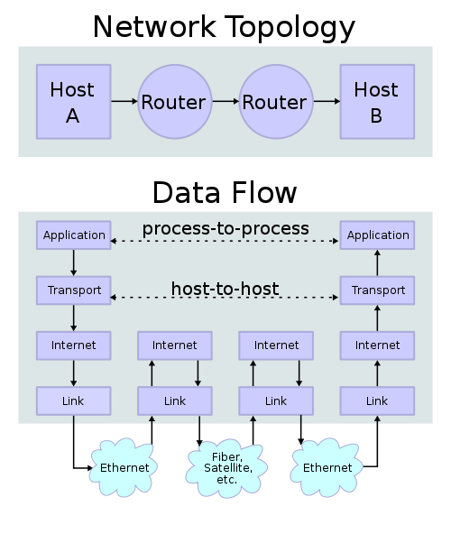
IP protocol stack
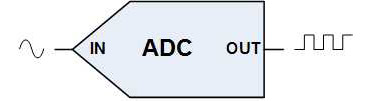
Audio enters the system via an analog-to-digital converter (A/D converter), often a sound card, at which point a computer program stores it as a file. These files can be .wav, .mp3, .mp4, apt-X, or some other format. Once the audio is converted to a digital data format, it is handled much the same way as any other digital data.
IP stands for “Internet Protocol,” which is a communications protocol for transmitting data between computers connected to area networks. In conjunction with a transmission protocol, either TCP (Transmission Control Protocol) or UDP (User Datagram Protocol) IP forms what is known as the Internet Protocol Suit known as TCP/IP. The Internet Protocol Suit contains four layers:
Application layer – This is the protocol that contains the end-use data. Examples of these would be HTTP, FTP, DCHP, SMTP, POP3, etc. Telos Systems uses its own application called “Livewire” for its equipment. Wheatstone uses “WHEATNET.” Digigram uses “Ethersound.” This is an important distinction.
Transfer layer – This contains the TCP or UDP header information that contains such things as transmitting, and receiving ports, checksum value for error checking, etc. It is responsible for establishing a pathway through multiple IP networks, flow control, congestion routing, error checking, and retransmission. TCP allows for multiple IP packets to be strung together for transmission, increasing transfer rate and efficiency.
Internet layer – This is responsible for transporting data packets across networks using unique addresses (IP addresses).
Link Layer – This can also be called the physical layer, using Ethernet (802.x), DSL, ISDN, and other methods. The physical layer also means things like network cards, sound cards, wiring, switches, and routers.
Advantages:
An IP network can be established to transmit data over almost any path length and across multiple link layer protocols. Audio, converted to data can thus be transmitted around the world, reassembled, and listened to with no degradation. Broadband internet connections using a cable, DSL, ISDN, or T-1 circuits can be pressed into service as STL’s, ICR’s, and TSL’s. This translates to fast deployment; no STL coordination or licensing issues, no antennas to install if on a wired network. Cost reductions are also realized when considering this technology over dedicated point-to-point TELCO T-1’s. Additionally, license-free spread spectrum radios that have either DS-1 or 10baseT Ethernet ports can be used, provided an interference-free path is available.
IP audio within facilities can also be employed with some brands of consoles and soundcards, thus greatly reducing audio wiring and distribution systems and corresponding expenses. As network speeds increase, file transfer speeds and capacity also increase.
Disadvantages:
Dissimilar protocols in the application layer mean a facility can’t plug a Barix box into a Telos Xtream IP and make it work. There are likely hundreds of application layer protocols, most of which do not speak to each other. At some point in the future, an IP audio standard, like the digital audio AES/EBU may appear, which will allow equipment cross-connections.
Additionally, the quality of the physical layer can degrade performance over congested networks. The installations must be carefully completed to realize the full bandwidth capacities of cables, patch panels, patch cords, etc. Even something as little as stepping on a Category 6 cable during installation can degrade its high-end performance curve. The cable should be adequately supported, not kinked, and not stretched (excessive pulling force) during installation.
TCP/IP reliability is another disadvantage over formats like ATM. In a TCP/IP network, no central monitoring or performance check system is available. TCP/IP is what could be called a “broadcast” protocol. That is to say, it is sent out with a best-effort delivery and no delivery confirmation. Therefore, it is referred to as a connection-less protocol and in network architecture parlance, an unreliable network. Lack of reliability allows any of these faults to occur; data corruption, lost data packets, duplicate arrival, out of order data packets. That is not to say that is does not work, merely that there is no alarm generated if an IP network begins to lose data. Of course, the loss of data will affect the reconstruction of the audio.
Analog digital converter symbol
Finally, latency can become an issue over longer paths. Every A/D converter, Network Interface Card (NIC), cable, patch panel, router, etc has some latency in its circuitry. These delays are additive and dependent on the length of the path and the number of devices in it.
Provided care is taken during design and installation, AOIP networks can work flawlessly. Stocking adequate spare parts, things like ethernet switches, NICs, patch cables and a means to test wiring and network components is a requirement for AOIP facilities.
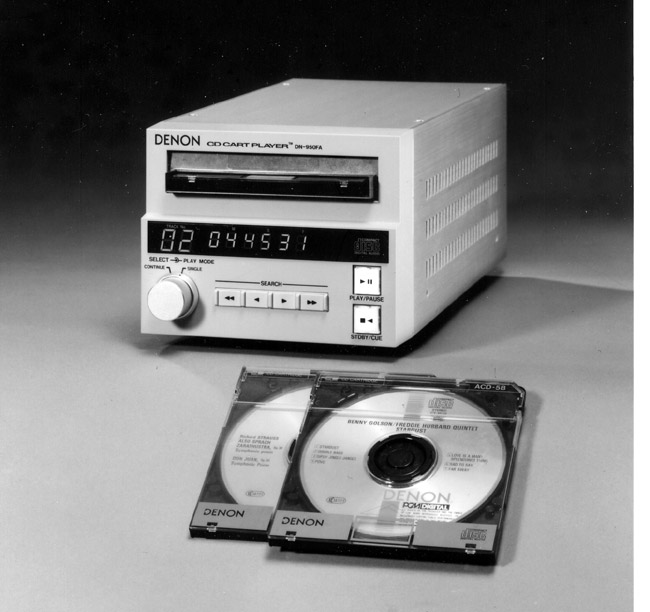
These were all the rage when they came out some 23 years ago or so. They were specifically made for DJs who were used to shuffling carts in and out of cart machines. The idea was to use familiar motions and procedures so DJs could easily perform their shifts using CDs without relearning studio dynamics. The only downside, a DJ could remove the CD that was playing by accident whereas pulling a playing cart out of a cart machine is difficult to do. Later Denon versions made it more difficult to remove playing CDs.
This is a promotions photo circa 1987.
Denon DN-950FA cart CD player
This machine is still in use 22 years after its manufacture date. Over the years the top cover has been removed countless times, no doubt to replace the KSS-210A optics and bearings or to periodically clean them. The Phillips head screws are so worn a screw extractor is nearly required.
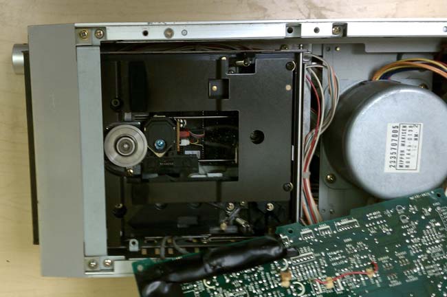
Denon DN-950FA backDenon DN-950 FA optics and platter
They are located under a circuit board, which has to be removed. Again, the DN-951 series CD players did away with this, making maintenance easier. These CD players could and often were affected by RF especially when the studios were co-located with an AM transmitter site. One such symptom was randomly speeding up and slowing down while playing. It made for some interesting-sounding songs and even more interesting commentary by the morning show.
Every time the optics and bearing were replaced, there was a pretty involved alignment procedure that took some time to get right. I remember some funny Japanese-to-English translations in the service manual.
Of course, nowadays if there are any issues, you just chuck the computer and get a new one.