The open delta three phase service

Several months ago, I drove up to an FM transmitter site, looked up at the utility pole, and saw this:

Three Phase open delta transformer bank

Three-phase open delta is a bad hombre.  Most, if not all, transmitter manufacturers will void the warranty of any transmitter connected to a service like this.  What is perplexing is it appears that all three phases are available on the primary side, why would this be necessary? Perhaps it was not always so at this location.  Regardless, this was the source of power for 20 KW FM transmitters since 1958 until we moved it to a new building last month.

According to a GE publication on transformers, open delta 3 phase power is undesirable because:

Although this connection delivers three-phase currents which are approximately symmetrical to a three-phase symetrical load, the currents flowing in the high voltage circuit are not equal nor are they 120 degrees apart.  The maximum safe output of the bank operating in this manner is 58% of a 3 pot Wye/Delta bank. The system is grossly unbalanced, both electrostatically and electromagnetically.

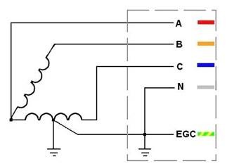
Schematically, it looks like this:

3 Phase open delta power

Regular 3 phase delta looks like this:

3 phase delta power
3 phase delta power

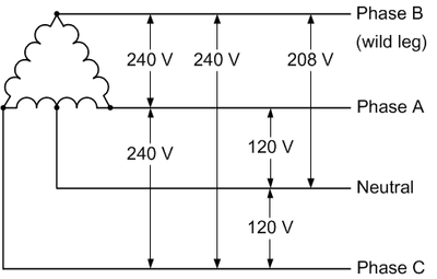
Most utility companies will not hook up 3 phase delta on the customer side anymore because the “high” or “wild” leg, which as shown in the diagram runs a good deal higher than 120 volts to neutral.  Hook up a high leg to a single phase 120 volt piece of equipment and wait for the power supply to blow up.  Also true with 277-volt lighting circuits, as my assistant once found out with the Coke Machine in the break room.  The new 3 phase service will almost invariably be 208 wye unless there is some very compelling reason, which is fine.

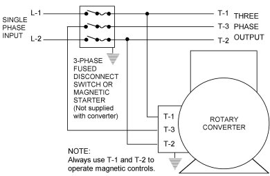
There are many ways to get around three phase open delta, perhaps the best is a rotary phase converter.  This piece of equipment will take a 240-volt split phase and add a third leg.  These legs will not be 120 degrees apart, as they would be in a true three-phase, however, they will be close enough that 3 phase motors and transformers will be happy.

Rotary Phase converter

This leads to an unbalanced voltage/current condition which needs to be accounted for in the design of the unit.  The second way to do this is to power a three-phase generator with a split-phase motor.  This will completely isolate the 3 phase equipment from the utility service and provide for true three phase power.

The downside to any motor/generator or rotary converter is moving parts and conversion inefficiencies.  At any transmitter site that uses this type of equipment, either a backup power converter or a lower power split phase backup transmitter should be installed.  With all mechanical things, eventually, this will need to be repaired and it would suck to be off the air while that is happening.

Regardless of any of that, this particular service is about to be disconnected permanently.  Good riddance.

The Generator and the UPS

An issue I had to deal with recently; was an unstable generator/UPS relationship.  When the generator was running under load, it surged repeatedly causing the UPS to drop out and not recharge.  Eventually, the UPS ran out of juice and shut down, killing the power to the Sine Systems remote control and telephone system.  Of the two, the remote control was the biggest pain to fix, as it lost its timed commands and would not reduce power at sunset for the associated class D AM station.

What went wrong?  This is a chart of typical problems with generators operating UPS loads:

SymptomPotential Problem
Fail to “lock on” to generator powerImproper generator frequency or voltage
Poor generator regulation
Unrealistic performance requirements
Instability of generatorVoltage regulator sensitivity
Control loop compatibility
Filter/control interaction
Governor or AVR problem
Fail to sync bypassMetering errors
Instability at specific load levelsControl loop compatibility
Instability at load changesControl loop compatibility
Metring errorsGenerator output voltage distortion
Loss of voltage controlExcess capacitance in filters vs. load

Table courtesy of Cummins Power Generation.

Generator excitation methods can be the culprit in many of these situations.  Generators often use one of three types of excitation for their field coils:

  • Shunt-excited SCR (silicon-controlled rectifier)
  • Shunt-excited PWM (pulse width modulation)
  • PGM (permanent magnet generator)

Of the three, the permanent magnet generator is the most stable since the AVR (automatic voltage regulator) is powered by a separate small generator which is unaffected by the load on the main generator output.  SCR and PWM both use the generator output windings, which makes them susceptible to load-inducted voltage distortion brought on by non-linear loads.  Therefore, in locations where large UPSs are known to be part of the load, PGM-excited generators are the best choice.

PMG generator diagram

Sometimes, the generator is already in use before the UPS is installed.  In that case, there are some remedial steps that can be taken.  The speed which the voltage regulator reacts to changes in the load is often the culprit in many of these situations.  It may seem counterintuitive, however, the faster the AVR reacts, the more fluctuations there will be in the voltage and frequency.  A UPS can operate under a wide range of voltages and frequency, provided they do not rapidly change.

Depending on other loads, it may be necessary to dampen the gain on the AVR to slow it’s reactions down.  This will work if there are no large intermittent starting loads on the generator such as air conditioning compressors.

Another method would be to delay the UPS transfer to generator power until after all the other loads have been satisfied.  This will ensure that the generator voltage and current fluctuations are damped by the existing load.

The generator’s size needs to account for the equipment attached to the UPS and the battery charging load. With a larger UPS, the battery charging load can be significant. Generators that are improperly sized will not be made to work under any circumstances, hence the “unrealistic performance requirements” noted in the chart above.

You can read the entire Cummins Power white paper on generators powering UPS loads here.

The Raytheon RM-10 Monitor Amp

I found this manual from 1946 in the drawer at the WICC transmitter site, which is a sort of time capsule due to its inaccessibility. I figured I would bring it home and scan it, then return it to the file drawer out on the island.  Step one is done:

Raytheon RM-10 Monitor Amp

This is a cool little monitor amp, capable of driving line-level or speaker outputs up to about 10 watts or so.  It could be used as a front or input stage for a larger audio amp.  By the way, 10 watts is a lot more than it seems, if using efficient speakers to convert that power into sound waves.  Specs show total harmonic distortion is between 0.6 to 2 percent depending on power and frequency.  Lower power output levels net less distortion.

Schematic is pretty simple, a pair of 6L6’s in push-pull for the output.   Inverse feedback into the previous stage via the output transformer.  Click on image for higher resolution.

Full manual and parts list is available here.

Now I just need to get the manual back out there.

The Gates BC250GY transmitter

This transmitter is in service at WSBS, Great Barrington, MA as a standby. It was new in January 1975.

Gates BC250GY transmitter, WSBS Great Barrington, MA

This was running into the dummy load for testing, which we try to do periodically.

Gates BC250GY AM transmitter audio section

The audio section is a pair of 8008’s 810s running in parallel. This goes through a modulation transformer to the RF section.

Gates BC250GY RF section

The RF section consists of another pair of 8008’s 810’s running parallel. The plate voltage for these tubes is 1,250 VDC which is fairly tame, all things considered. The transmitter is dirt simple 250-watt carrier power, 125% positive peak capable.  It is not the most efficient unit under the sun but it can still be repaired with off-the-shelf parts.

Gates BC250GY Schematic

This is a somewhat faded schematic.  The schematic shows a single 833A as the final, however, this particular transmitter has a pair of 810’s for the final, as shown in the above picture.  Ham radio operators love these things as they are easy to convert to 160 or 80 meters for AM phone use. The bigger brother to this unit is the Gates BC1G, which is also a pretty simple unit using 833A tubes in parallel with 3,500 VDC plate voltage.