We were notified that the WFAS-AM tower lights were out, thus, it was time to investigate. This problem was easy to find. Upon removing the waterproof cover on the tower light flasher box, I found this:
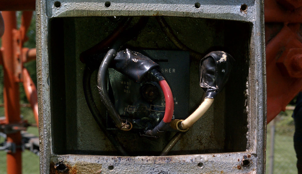
As soon as loosened the screws on the cover, I smelled the unmistakable odor of burned electronics and plastic. I disconnected the flasher and covered the photocell, which turned the side markers on. Of course, the top flashing beacon was dark, therefore, it was time to report the outage to the FAA. The nationwide number to report tower light outages is (877) 487-6867. That number is for an automated system, however, eventually, it leads to a live person. Since the new reporting system was established, the only required information is the tower ASRN. From that information, the operator will access a database and have all the required information to issue a NOTAM. In the past, many questions were usually asked; what is the nearest airport, how far away is the airport, how tall is the obstruction, what is the position, etc? Therefore, things have become slightly easier than before.
Once the outage is reported and a NOTAM is issued, the tower owner generally has fifteen days to correct the problem.