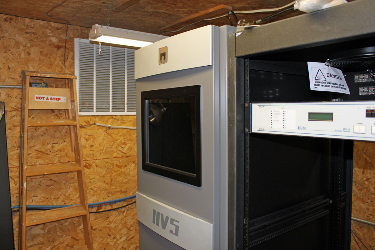
We are currently installing this sweet little transmitter:
Nautel NV-5 FM transmitter
Like its big brother, the NV-40 at WVPS, the NV-5 is a very cool transmitter. I am a born skeptic, things like touchscreen displays tend to make me a little nervous, especially on a transmitter connected to a 350 feet tall steel tower right next to the transmitter building. That is the one major difference between WVPS and this site; at Mount Mansfield there are many things between the transmitter and antenna, but in this place, not so much. Even so, Nautel makes a good product, so troubles are not expected.
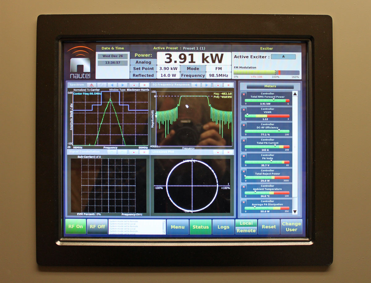
The ground strap, AC power, remote control, and composite audio connections were all made without difficulty. The result, new transmitter on the air:
Nautel NV-5 FM transmitter GUI
This unit is analog only, but the information on the spectral display is still useful. The GUI uses Linux with a touch screen, which is a neat feature.
Nautel NV-5 FM transmitter controller board
In case the front panel GUI goes out, all transmitter controls can be accessed via push buttons on the remote control interface, which is the small board to the right. The main controller board is on the left.
After extensive testing of Both HD Radio and DRM, the Secretary of the Ministry of Communications Electronic Communications, Genildo Lins, said the tests of the two technologies have had poor results, especially high-power FM . The testing demonstrated the digital signal coverage is approximately 70% of the current analog signal. “The future of radio is digital, but that future is not yet. We are unable to make a decision on these results.” A polite way of saying “This is not the digital radio we were hoping for.”
These are just a few brief excerpts of the FM HD Radio test reports from Sao Paulo. The method of testing:
The transmission system was located in the center of the city of São Paulo. The signal HD Radio digital broadcast was extended hybrid mode combined with the analog signal in the air, with separation of 163.8 kHz from the carrier’s analog FM signal and the carriers of HD Radio digital signal in sub-upper and lower sidebands. The power used in transmitter for the analog signal was 27 kW, and for the digital signal of 1 kW. Attaching the FM and HD Radio systems in their respective transmission antennas, the power Isotropic Effectively Irradiated (EIRP) of the analog signal was 112.3 kW and the digital signal of 1.12 kW. Thus, the protection ratio (EIRP power ratio between the analog and digital signals) was 20 dB (sic). During the measurement campaign, two commercial FM receivers were used analysis of analog reception, both to verify their potential impacts on receiving due the introduction of the digital signal, as to assist in verifying the coverage area of the signal analog.
The results of this testing:
Checking the results on each route, the route R1 radial (southeast direction), the stretch P1 to P2, that extends to 10.88 km (7.3 miles) of distance from the transmitter, the audio decoding was 71.6% of the digital audio frames received, and in the remaining sections of the route were little digital coverage.
In radial route R2 (southwest direction) was decoding of digital audio throughout the stretch to P1 P2, which extends up to 10.7 km (6.6 miles) of distance from the transmitter. In the following passage (P2 P3), the first blend was 17 km (10.5 miles) from the station. Following the passage P3 to P4, 26.4 to 44.9 km (27.9 miles), there was only 21.8% decoding of digital audio frames received within that stretch. In the last section (P4 to P5), from 44.9 km, there was almost no coverage digital.
In R4 route (northwest), there was decoding of digital audio throughout the stretch P1 to P2, extending up to 11.8 km (7.3 miles) of distance from the transmitter. In the following passage (P2 P3), from 11.8 to 24.9 km, was 62.5% of decoding digital audio frames received within that stretch. Following the stretch from 24.9 to 47.5 km (29.5 miles), (P3 to P4) the percentage was 24.3%. In the last stretch, from 47.5 to 61.7 km (P4 to P5), no digital coverage.
In route R6 (northeast direction), the stretch up to 9.8 km (6 miles), (P1 to P2) was 74.7% decoding of audio frames. In the passage P2 to P3 from 9.8 km to 29.8 km (18 miles) of the station, there was audio decoding 100% of the received frames. Following the stretch from 29.8 to 45.3 km (28.1 miles) (P3 to P4), the percentage was 87.2%, and in the last stretch, from 45.3 to 60.9 km (P4 to P5), the percentage was 47.9%.
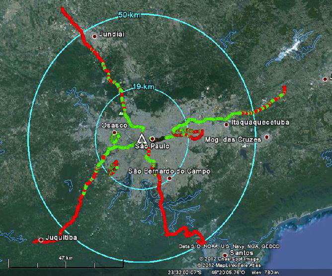
Routes are shown on a map:
Using unbiased real-world testing, HD Radio does not look so hot. One caveat; the digital carrier level is -20dBc. That being duly noted, results show a 112 KW EIRP analog station with a 1.12 KW digital carrier that is unusable 6 miles from the transmitter site in some areas. It is almost hard to believe. Original documents can be found on the Government of Brazil Ministry of Communications website (in Portuguese). They are interesting reading, although you may need to parse them through Google translator.
AM HD Radio (no surprise) and DRM have similar or worse results.
Thus the myth “Digital is better,” is called to question. I am not opposed to new technology, provided it works better than the technology it is replacing.
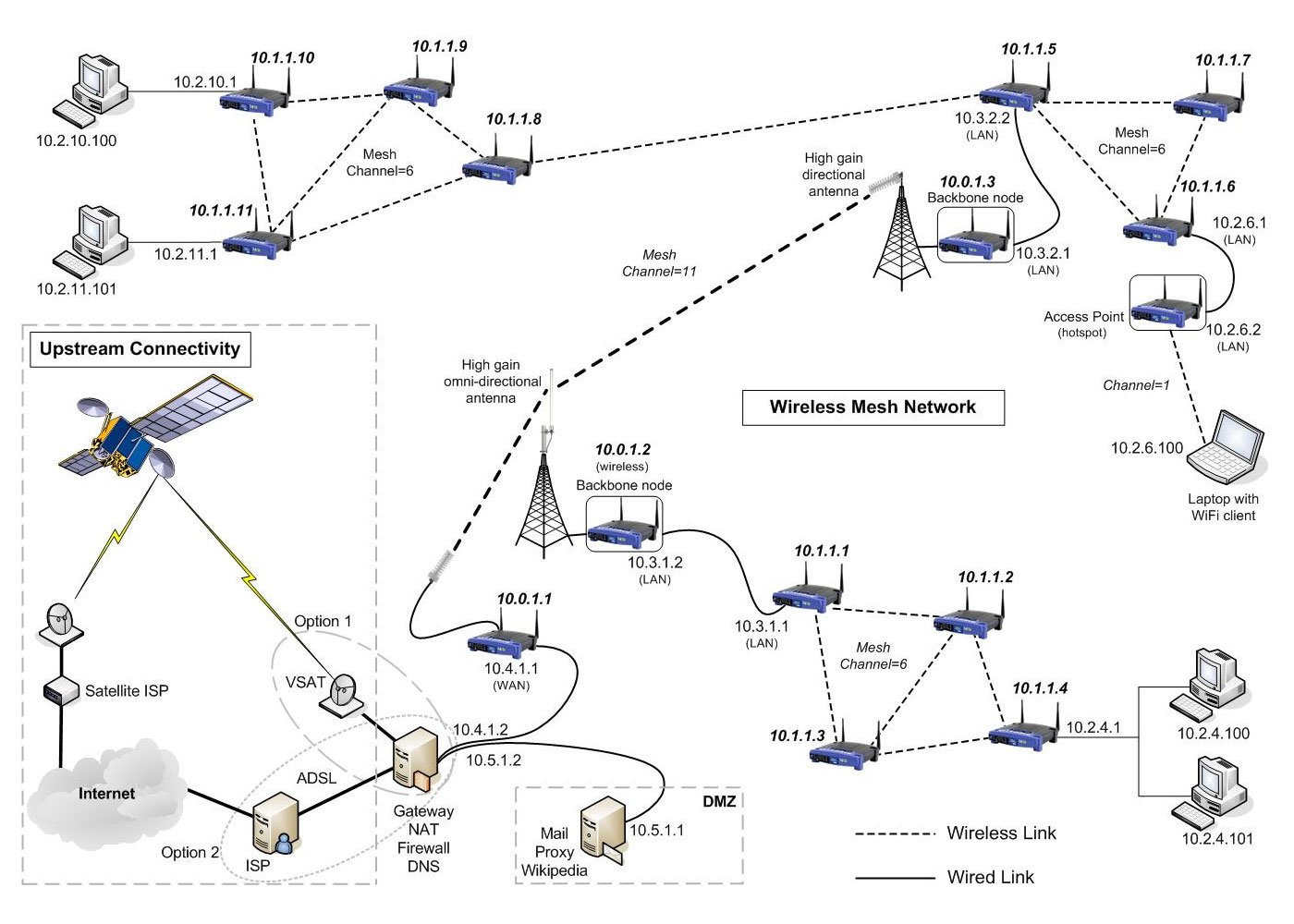
Wireless IP Ethernet (802.11) technology has been around for a while. Many know it as “WIFI” but you could also call it “WLAN” or something similar. Like many other Ethernet technologies, WLAN relies on a spoke and hub connection system. The hub is the wireless access point or router and the individual hosts (PCs, tablets, phones, etc) are the end point for each connection. In a wired network, it is usually some type of switch that forms the center of the network data distribution system.
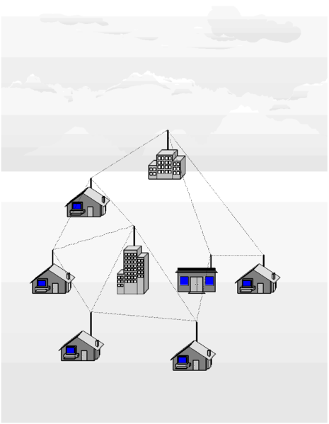
With a wireless mesh network or ad hoc network (802.11s), each wireless device can connect to any other wireless device within range. In this type of peer-to-peer network, there is no central access point, although something can act as an internet gateway or there can be several gateways. This type of topology functions much like the public network (AKA the internet), where there are many different paths to anyone (major) destination. If any one of those paths goes down, another route is quickly found.
This technology was developed by several vendors for military communications systems and for OLPC (One Laptop Per Child) programs in Africa and other places. Each link acts to extend the boundaries of the network, thus the more users there are, the more useful the network becomes.
Wireless Mesh Network diagram
Advantages of mesh networking:
Networks are self-forming; once the nodes are configured and can see other network nodes, the network automatically forms
Networks are self-healing; if one node drops offline, traffic is automatically routed to other nodes. If the node comes back up, it is included back into the network
High fault tolerance; in areas where many nodes exist and can see each other, the failure of any single node does not affect the rest of the network
Low cost to deploy; mesh networks use standard off-the-shelf WLAN (802.11) devices. The choice of software will dictate which hardware will work the best
Crowd-sourced infrastructure; as each network node is owned by an individual, the cost and responsibility is shared among the community
Several specific routing protocols have been developed for the network side of the system. Hazy Sighted Link State Routing Protocol (HSLS), BATMAN, OLSRHWMP and others. These work well with the existing 802.11 a/b/g wireless network hardware currently available.
On the host side, a good IBSS-capable wireless network adapter is needed, which many of the newer ones are. Several of the software programs have lists of WLAN adapters that work with their software. Open Garden is a free App for Windows, Mac OSX, and Android, and they are working on an iOS version. This leaves out certain devices like tablets and iPhones for now.
Since existing wireless adapter drivers do not yet support mesh networking, usually an additional piece of software is needed. There are several interesting ones, including HSMM-MESH, which was developed by Amateur Radio operators. Open-source programs for Linux, Free BSD and other are available as well as commercial versions for Windows.
I was thinking that this might be useful for broadcast applications. For obvious reasons, this type of system would work best in densely populated urban and suburban areas, which is exactly the type of area in which LPFM licenses might be hard to come by. For those who do not have the time or wherewithal to apply for an LPFM license, or for those that simply don’t get a license due to scarcity of available channels, this could be a great way to cover a neighborhood or section of a city. The more people participate in the mesh network, the stronger the network becomes. Additionally, by using FCC type accepted part 15 FM and AM transmitters as broadcast nodes, carrier current transmitters, and leaky coax systems, the presence of the mesh network can be advertized to potential listeners, including directions on how to take part.
Wireless mesh network example, courtesy of Meraka Institute
Wireless LAN bridges or broadband internet connections can act as a backbone between distant nodes.
For bandwidth efficiency sake, AOIP services should be limited to multicast addresses.
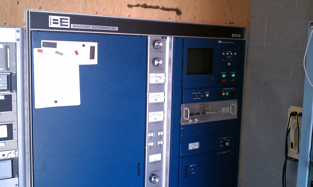
Guess what caught fire this time? It’s this thing, which has become the newest piece in my burned-up shit collection:
BE FM30A IPA regulator board
If you give up and are totally flummoxed, this is the IPA power supply regulator for a BE FM35A transmitter. Here it is in better days when it was actually working. The IPAs are in pull-out drawers on the right side of the transmitter cabinet, below the FX-30 exciter.
BE FM35A transmitter, on air
Said transmitter is aging not so gracefully, as it turns 26 this year. There does seem to be a finite life to transmitting equipment, something that should be kept in mind when planning out next year’s capital expense budgets. Regardless of all that, this event naturally occurred the day after Thanksgiving.
The good news, and there is always good news, we have many spare IPA regulators and PA modules in the shop ready to go. Upon investigation, there were numerous other problems with this transmitter, which have been or will be addressed.