I was working on a Harris SX5 the other day and snapped a picture of the scope while measuring RF drive levels. There are still quite a few of these units out in the field, judging from my search engine results. I thought it would be helpful to post something about it. The RF power amp boards for the Harris Gates solid-state AM series transmitters are the same design, I believe.
In order to fully drive the RF MOSFETs in this particular series of transmitters (Harris SX1, 2.5, and 5 including A models) at least 26.5 volts peak to peak is required. Less than that and the device will turn full-on and internally short. To measure RF drive, the transmitter must be in local with control voltage on, with the rear door interlock defeated (this can be safely done if the transmitter is wired with separate AC feeds for control and RF power supply). Make sure the RF power supply is defeated and will not turn on. Measure across the input of each of the toroids that feed the gates of the RF devices.
It should measure between 26.5 and 29.5 volts. This one measures 27.45 volts peak to peak. Each input toroid on every PA board should be measured as the toroids themselves have strange failure modes and may pass resistance and continuity tests, yet still not provide proper drive voltage to the attached devices. This has to do with core permeability. Each toroid feeds two RF MOSFETs, replace part is IRF-350.
As always when dealing with an SX transmitter, good luck.
Today there will be a quiz. Ready? Look at this picture and see if you can spot the problem:
Problem with Harris SX2.5A transmitter
If you said “Hey, that green wire seems a little odd; it disappears behind the heat sink next to that screw then reappears again at the top,” you are correct. What really sucks is the green wire is the transmitter off connection to the remote control. So, when the PA board was secured to the heat sink, the wire was trapped between the board and the heat sink. Since the components were cold, they did not pinch through the insulation right away, no. Rather, after the transmitter ran for several hours at full power, it got hot enough to displace the wire insulation and cause a short. Doh! The transmitter is off and it won’t come back on!
This is a picture of the wire after it was removed:
Pinched wire
Haste makes waste. Unfortunately, it was someone else’s haste that ruined my Saturday afternoon when I was supposed to be taking my son to little league practice. I am sure that some not-so-kind words will be exchanged very soon.
Most broadcast facilities have an engineering department or service and an IT department or service which are separate. There is often a fuzzy line between what machines belong strictly to engineering and what belongs to IT. There are several different systems that have network interfaces but are not generally considered computers and fall squarely in the engineering department. These include such equipment as transmitters, satellite receivers, EAS machines, IP-based audio routers and audio consoles, and IP audio CODECS. In many cases, windows based automation systems and servers also fall under the responsibility of the engineering department.
As the recent incidents of network intrusions into vulnerable EAS machines show, after installation, steps must be taken to secure networked equipment from malicious or accidental intrusions. The aforementioned EAS intrusion was bad but it could have been much worse.
Anything with a network interface can be exploited either internally or externally and either by purpose or accident. The threat plan looks like this:
Computer network intrusion plain
Every unauthorized network access incident falls somewhere on this plain. An unauthorized network intrusion can be as simple as somebody using the wrong computer and gaining access to back-end equipment. It can also be the hacker or cracker from a foreign country attempting to breach a firewall.
Basic network security falls into these categories:
Physical security of machine or server room
Security against internal accidental or malicious use
Security against external intrusion
Protection against malicious software exploitation
The first category is the easiest to understand. Physical security means securing the server room through locking doors and preventing crawl-over/under entries. Security cameras and monitoring are also a part of physical security. Something that is often neglected is extended networks that bridge to transmitter sites. Non-maned off site facilities that have network access are vulnerable points if multiple clients or tower tenants have access to the same room. Locked equipment racks and video cameras are two ways to secure non-maned transmitter sites. Also, when using good quality, managed switches at transmitter sites, switch port security features can be enabled, and unused switch ports shut down.
Accidental or malicious internal intrusions can be reduced or eliminated with proper password policies. The first and most important password policy is to always change the default password. There are lists of default routers and switch passwords available online. The default passwords for EAS machines and other equipment is published in owner’s manuals and most broadcast engineers know them by heart. Always change the default password, if you do nothing else, do this.
Other password policies include such things as minimum password length, requiring special characters, numbers and both upper and lower case letters. Even taking those steps, passwords are still vulnerable to dictionary attacks. To prevent a dictionary attack, the login attempts should be limited to five or so with a thirty minute freeze out after the attempt limit is reached.
External intrusion can come from a number of different sources. Unsecured WIFI is the easiest way to gain access to a network. Always secure WIFI with WPA or WPA2 AES encrypted pre-shared key. This will keep all but the most determined intruders out. Other external threats can come from man in the middle attacks. IP bridges and WIFI must always be encrypted.
External attacks can also come over the wired network. Most small routers have default network and password settings. I have started moving away from using 192.168 internal networks. Router firewalls and personal software firewalls are effective but not foolproof. Software updates need to be performed regularly to be effective. One recently discovered exploit is UPnP, which is enabled on many home and small office routers. UPnP (Universal Plug-n-Play) SSDP (Simple Service Discovery Protocol) can be exploited of exposed to the public network side of the router. ShieldsUP! by Gibson Research Corporation is a good evaluation tool for router exploits, leaks and phone homes. They also have links to podcasts and youtube videos.
Disabling unused features on routers is a good security policy. Features such as DHCP, DNS, SNMP, CDP, HTTP server, FTP server etc are all vulnerable to exploitation of one form or another. Turning off those protocols that are not in use will eliminate at least a portion of those threats.
Finally, worms, bots, viruses and other malicious software can come from anywhere. Even reputable websites now have drive-bys in linked advertizing banners. Non-windows operating systems are less vulnerable to such programs, but not immune. All windows machines and servers that are in anyway connected to the internet need to have updated antivirus software. Keyloggers can steal passwords and send them to bad places where people have nefarious intent.
There are entire books, standards and upper level classes taught on network security. This less than 1,000 word article barely brushes the surface, as the titles says, these are but a few very basic ways to implement a security policy. It is important for technical managers and engineers to learn about, understand and implement security policies in broadcast facilities or suffer the consequences of complacency.
Something that I eluded to in a previous post, we finalized the move of the WSBS translator, W231AK, from the Fairview Hospital in Great Barrington to the side of the AM tower.
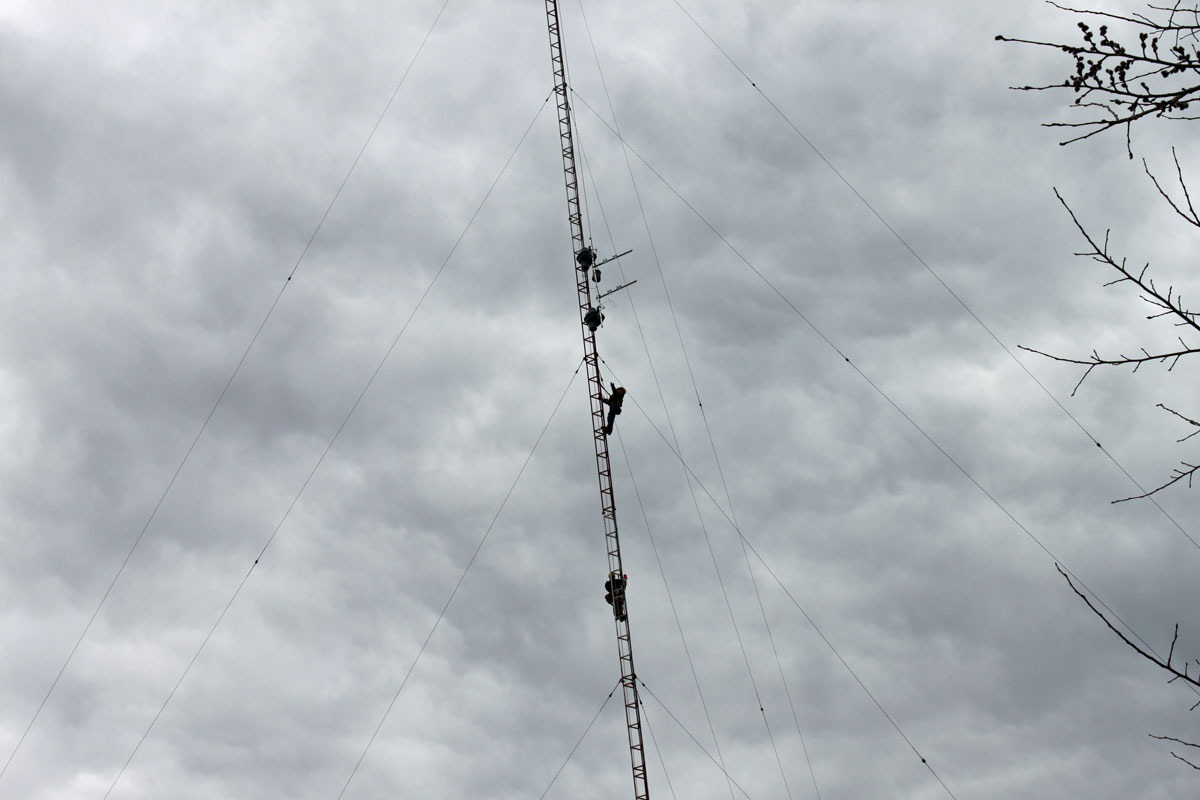
Tower crew hanging translator antenna on AM tower
The move was started by hanging a new Shively 6812B antenna from the side of the AM tower, located off of US 7, north of Great Barrington. This is a half-wave-spaced circularly polarized antenna.
While this work was going on, some guy from OSHA showed up and started taking pictures without asking permission or telling anyone who he was. We informed him that he was on private property and asked him his reasons for being there. He got in his car and left, no doubt to a parking lot down the road so he could keep the tower climbers safe… mostly from themselves… by levying huge fines for free climbing… Wasn’t there something in the news about the government running out of money? Anyway…
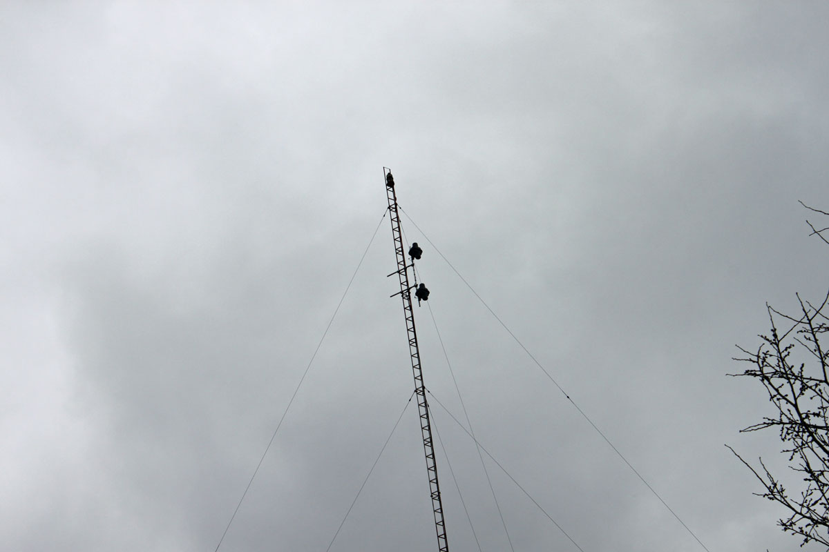
W231AK antenna, Great Barrington, MA
WSBS had been using this translator for a few years. The advantages for the station from the translator move are greater power output (from 35 watts to 250 watts ERP) and less operating expenses in the form of TELCO line charges and roof top rental at the Hospital.
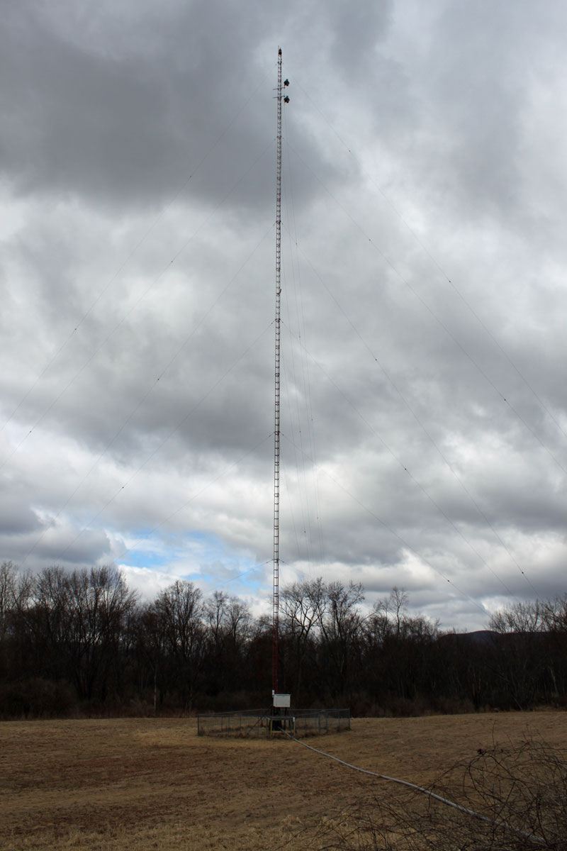
WSBS tower with W231AK antenna mounted
In addition to that, the reliability of the translator should increase, as there have been several instances in the past when TELCO line problems have taken the translator off the air for days at a time.
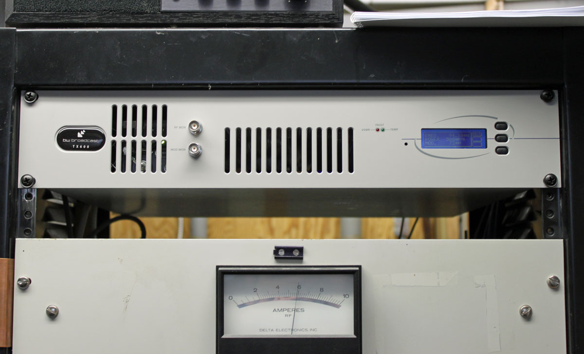
W231AK new transmitter, WSBS base current meter below
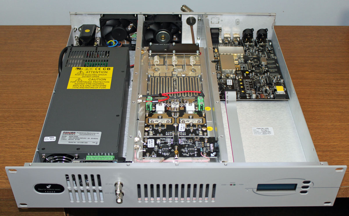
The transmitter for W231AK was changed from a Crown 35 watt unit to a BW Broadcast T600. These units are made in the UK and it is an all-in-one processor/exciter/transmitter. We took the cover off to make a few configuration changes and the entire unit is very well made.
BW Broadcast T600 insides
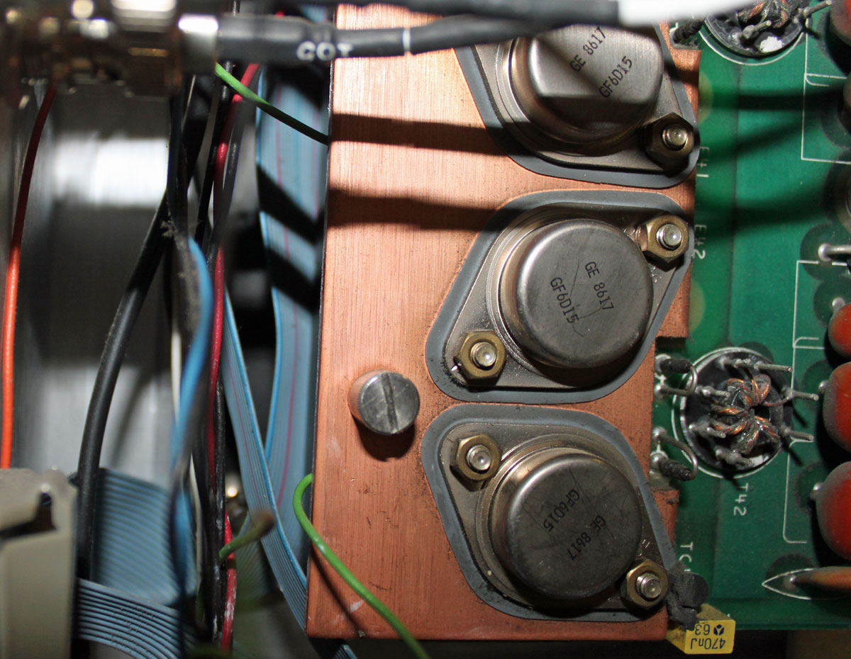
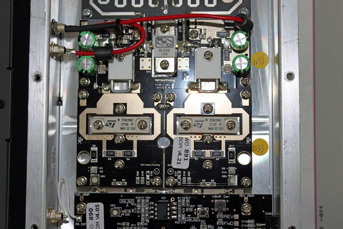
One of the nice features of this particular transmitter is the screw-down clamping method of connecting the RF devices. Lets face it, unsoldering MOSFETS is a PITA. This screw down clamp eliminates all that.
BW Broadcast T600 power amp
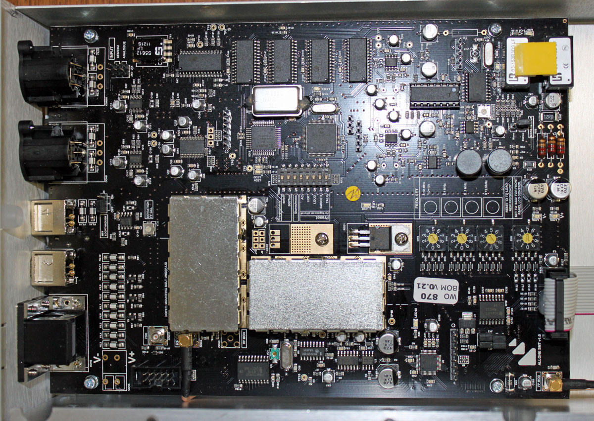
The audio input and processing board is pretty neat too.
BW Broadcast T600 audio input board
There are several different processing settings which we played around with. All in all, it seems like a pretty solid unit and I would recommend it to anyone looking for a low to moderate power transmitter.