Had a problem with this Kintronic FMC-0.1 isocoupler the other morning.

After an overnight drenching heavy rain and very high wind, the STL transmitter associated with this unit was having high VSWR faults. This isocoupler crosses a base insulator of an AM 50 KW directional antenna. This particular tower has negative impedance, which is to say, it sucks power out of the pattern and feeds it back to the phasor. An interesting discussion for another time, perhaps.
Using a dummy load, we isolated the problem to the isocoupler by first connecting the load to the output on top of the unit (the problem still exists) and then to the transmission line prior to the unit (the problem went away). Of course, the AM station had to be taken off the air to do this work.
Once the issue was confirmed as the isocoupler, I opened the unit up and found that water had entered and pooled in the top of the bottom half of the isolation transformer.
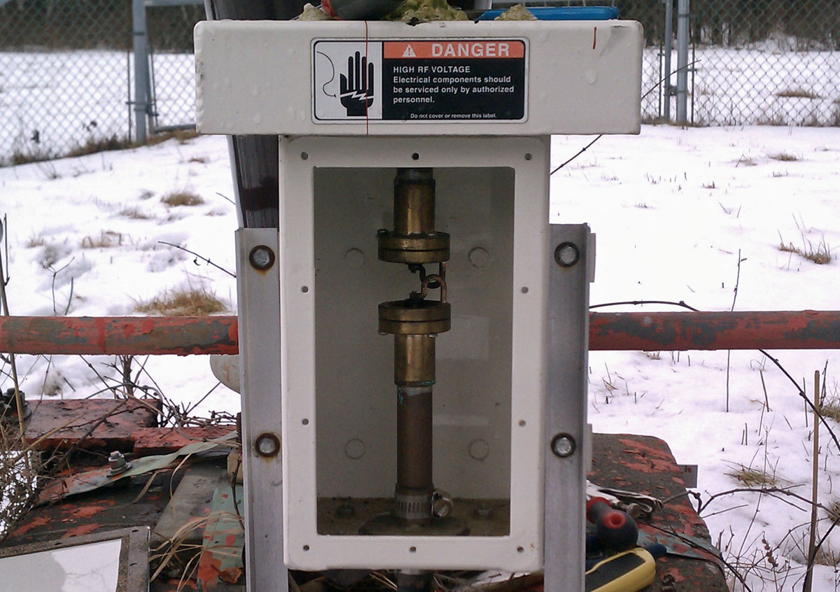
The isolation transformer consists of two loops to ground capacitively coupled through air dielectric. The issue is with the opening around the top of the unit, under the lip of metal lid. Apparently, this allowed water in.
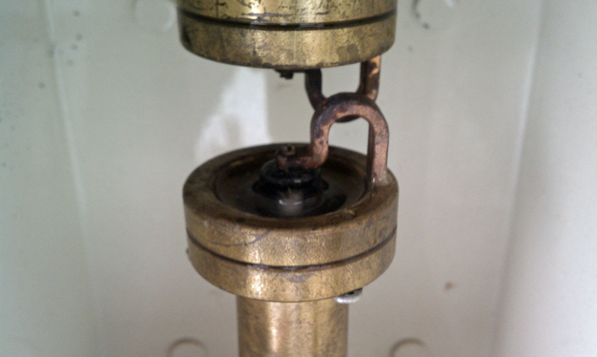
It is difficult to tell with the lighting in this photograph, however, the bottom part of this isolation transformer has water pooled around the center insulator. Using a rag, I cleaned out the water and dirt from the center insulator. After reconnecting the antenna and transmitter transmission line, a quick check revealed the problem was much better, but still not completely gone. I suspect water seeped further down into the bottom half of this unit. The repair work was good enough, however, to return both stations to the air.
Glad to get that bit of work done while it was still relatively warm out.