This is a rule that I always find difficult to enforce. Since switching into contracting mode, I am often at any particular studio once per week or less. It seems to me, no matter what signs are posted or what words are spoken, the DJ seems to hear; “It is okay to eat and drink in the studio.”
Of course, with that attitude, the inevitable is bound to happen:
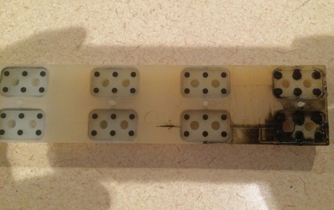
RS-18 Millenium console on/off button membrane
To make things worse, this was spilled on the main mic on/off buttons. These button membranes come in groups of six and are not inexpensive. The complaint was “The main mic will not turn off.” Ah well, I am paid to fix things after all. The DJs are only inconveniencing themselves at this point.
Remember way back when, perhaps in high school or college, you met this really cool person who seemed to be wonderful in every way? Yeah, then you got to know them a little better, and, well, those first impressions changed a little bit.
Crossed Field Antenna, Courtesy of Wikipedia
The Crossed Field Antenna (CFA) sort of reminds me of my first prom date. There was a lot of promise there, but plans fell through.
From a 1999 Radio World article:
Imagine an AM antenna one–fiftieth of a wavelength long, that needs no radial ground system, occupies a small parcel of land, produces little or no RFI (Radio Frequency Interference), has great bandwidth and performs better than a full–sized vertical radiator.
This potential new antenna was all the rage during the early 00s or whatever you call that decade. I remember thinking to myself; I will believe it when I see the test results. At one point, there was a battery of tests run in the installation in Egypt and China. The test results are spotty at best, however, none of these installations performed up to expectations. While it looks like a cool idea, and it would have been great to see it succeed, it seems that sheer willpower alone will not make a particular system work outside of the laws of physics. There are a few of these still in operation out in the wild, mostly in Egypt.
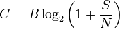
A theorem is not, indeed, a fact. It is rather, an idea that is deduced and supported by other proven facts. Thus, a theorem is generally believed a truth. It should be of interest to the “All Digital” AM (AKA Medium Wave) proponents that noise on the digital channel will reduce data throughput as a function of channel bandwidth and Signal to Noise Ratio. This is known as the Shannon-Hartley theorem:
Where: C is the channel capacity in bits per second; B is the bandwidth of the channel in hertz (passband bandwidth in case of a modulated signal); S is the average received signal power over the bandwidth (in case of a modulated signal, often denoted C, i.e. modulated carrier), measured in watts (or volts squared); N is the average noise or interference power over the bandwidth, measured in watts (or volts squared); and S/N is the signal-to-noise ratio (SNR) or the carrier-to-noise ratio (CNR) of the communication signal to the Gaussian noise interference expressed as a linear power ratio (not as logarithmic decibels).
With this equation, one can discern a fundamental flaw in all digital logic. One of the main issues with AM Medium Wave broadcasting is the ever-increasing noise floor. Our society has changed drastically in the last one hundred years or so since AM was invented. Electrical noise generators; computers, plasma screen monitors, mobile phones, appliances, energy-efficient lighting, data over power line, street lights, poor utility line maintenance, and even electric cars, it seems, generate a cacophony of noise in the Medium Wave frequency band. A digital modulation scheme, be it HD Radio or DRM, will mask the noise to a certain extent, that is true. However, once the SNR exceeds the ability of the receiver to decode the necessary bits, the receiver will mute. While it is true, the listener will not hear noise, they may not hear anything at all.
I will also note; none of the current “AM improvement” schemes under consideration by the FCC addresses the noise issue on the AM band. Without addressing the noise issue, any digital modulation scheme will be a temporary fix at its very best. The noise floor will continue to rise and after it gets high enough, the all-digital modulation will simply not work.
It will be interesting to see the data from the all-digital HD Radio testing that is being done in various locations. That is, if the NAB, et al. does not decide to treat that data like some kind of state secret; they have become reticent of late. When somebody acts like they have something to hide, it makes me think they have something to hide…
More and more wireless LAN links are being installed between the transmitter and studio. Often these links are used for network extension, remote control, site security, VOIP telephony, and sometimes even as a main STL. These systems come in several flavors:
Moseley LAN link or similar system. Operates on unlicensed 920 MHz (902-928 MHz) band. Advantages: can use existing 900 MHz STL antennas, can work reliably over longer distances, transmitter, and receiver located indoors. Disadvantages: slow, expensive
ADTRAN TRACER or similar system with indoor transceivers and coax-fed antenna systems. Operates on unlicensed or licensed WLAN frequencies. Advantages: fast, transmitter and receiver located indoors, can be configured for Ethernet or T-1/E-1 ports. Disadvantages; expensive
Ubiquiti Nano bridge or similar system where the transceiver is located in the antenna, the system is connected via category 5/6 cable with POE. Operates on unlicensed or licensed WLAN frequencies. Advantages; fast, relatively inexpensive. Disadvantages; equipment located on the tower, difficult to transition base insulator of series fed AM tower.
Ubiquiti Rocket or similar system where the antenna and transceiver are separate, but the transceiver is often located on the tower behind the antenna and fed with category 5/6 cable with POE. Operates on unlicensed and licensed WLAN frequencies.
For the first two categories of WLAN equipment, standard lightning protection measures are usually adequate:
Good common point ground techniques
Ground the coaxial cable shield at the tower base and at the entrance to the building
Appropriate coaxial-type transmission line surge suppressors
Ferrite toroids on ethernet and power connections
For the second two types of WLAN equipment, special attention is needed with the ethernet cable that goes between the tower and POE injector or switch. Shielded, UV-resistant cable is a requirement. On an AM tower, the shielded cable must also be run inside a metal conduit. Due to the skin effect, the metal conduit will keep most of the RF away from the ethernet cable. Crossing a base insulator of a series excited tower presents a special problem.
The best way to get across the base insulator of a series excited tower is to use fiber. This precludes the use of POE which means that AC power will be needed up on the tower to power the radio and fiber converter. This may not be a huge problem if the tower is lit and the incandescent lighting system can be upgraded to LEDs. A small NEMA 4 enclosure can house the fiber converter and POE injector to run the WLAN radio. Some shorter AM towers are no longer lit.
Another possible method would be to fabricate an RF choke out of copper tubing. This is the same idea as a tower lighting choke or a sample system that uses tower-mounted loops. I would not recommend this for power levels over 10 KW or on towers that are over 160 electrical degrees tall. Basically, some 3/8 or 1/2-inch copper tubing can be wound into a coil through which a shielded ethernet cable can be run. Twenty to twenty-five turns, 12 inches in diameter will work for the upper part of the band. For the lower part, the coil diameter should be 24 inches.
In all cases where CAT 5 or 6 cable is used on a tower, it must be shielded and the properly shielded connectors must be used. In addition, whatever is injecting power into the cable, ether POE injector or POE switch must be very well grounded. The connector on the shielded Cat5 or 6 cable must be properly applied to ensure the shield is grounded.
In addition to that, some type of surge suppressor at the base of the tower is also needed. Tramstector makes several products to protect low voltage data circuits.
Transtector APLU 1101 series data line protector
These units are very well made and designed to mount to a tower leg. They come with clamps and ground conductor designed to bolt to a standard copper ground buss bar.
Transtector APLU 1101 series data line protector
There are various models designed to pass POE or even 90 VDC ring voltage.
Transtector APLU 1101 series data line protector
This model is for POE. The circuit seems to consist mostly of TVS diodes clamping the various data conductors.
As more and more of these systems are installed and become a part of critical infrastructure, more thought needs to be given to lightning protection, redundancy and disaster recovery in the event of equipment failure.