One of those things that I have written about before, but seems to be common these days as older AM towers need to be replaced. One of our clients had just such a tower. Erected in 1960, the hollow-leg stainless tower was rusting from the inside out. When the tower crew came to put up the translator antenna, they discovered that there was a hole in one of the legs and climbed back down.
The tower’s condition was somewhat known, there were braces installed several years ago at certain levels to keep the tower standing. The new owner had planned to replace the tower eventually, so those plans were moved ahead.
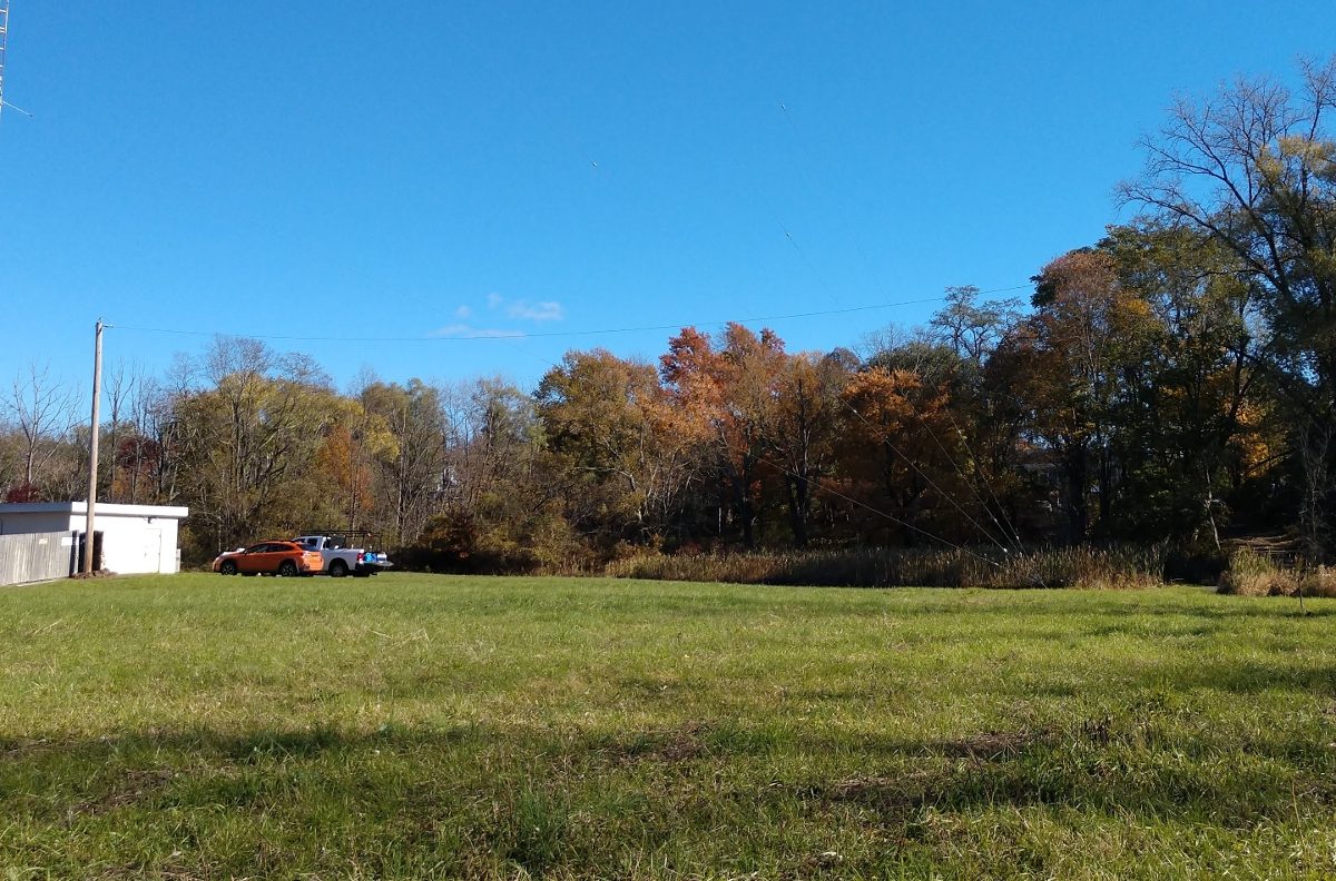
A temporary utility pole was installed near the transmitter building and a wire was strung to another customer-owned pole about 170 feet away. At 1,490 KHz, that proved to be a pretty good length. The issue with these medium wave temporary antennas is always the height above ground. In order for the radiation resistance to be somewhat reasonable, the antenna needs to be at least 1/8 to 1/4 wavelength above ground. That means a minimum of 78 to 157 feet at 1,490 KHz. The utility pole installed is 35 feet AGL.
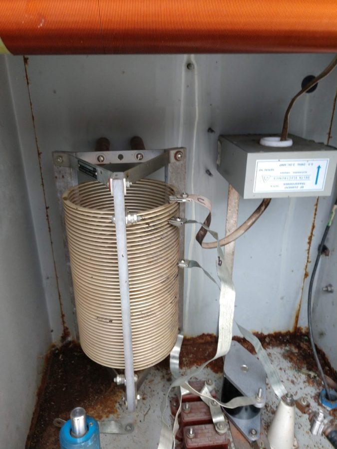
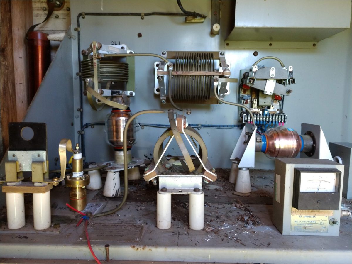
Thus, the wire antenna has a fairly low resistance, with loads of inductive reactance. Something on the order of 20 ohms, +j480. Since this is temporary, we reused the existing ATU that was designed for the series excited tower. With a capacitor installed on the incoming wire to cancel out some of the inductive reactance, a simple T network was configured to match the 50-ohm transmitter output to the 20-ohm antenna.
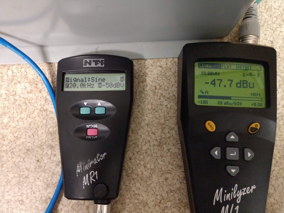
In the end, we were able to run about 400 watts into the wire, which covered the city of license fairly well. While the new tower was being erected nearby, we had to reduce that to about 100 watts to protect the tower workers from the hazards of non-ionizing radiation.
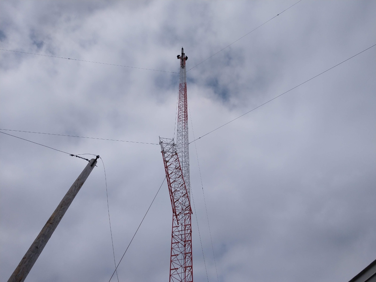
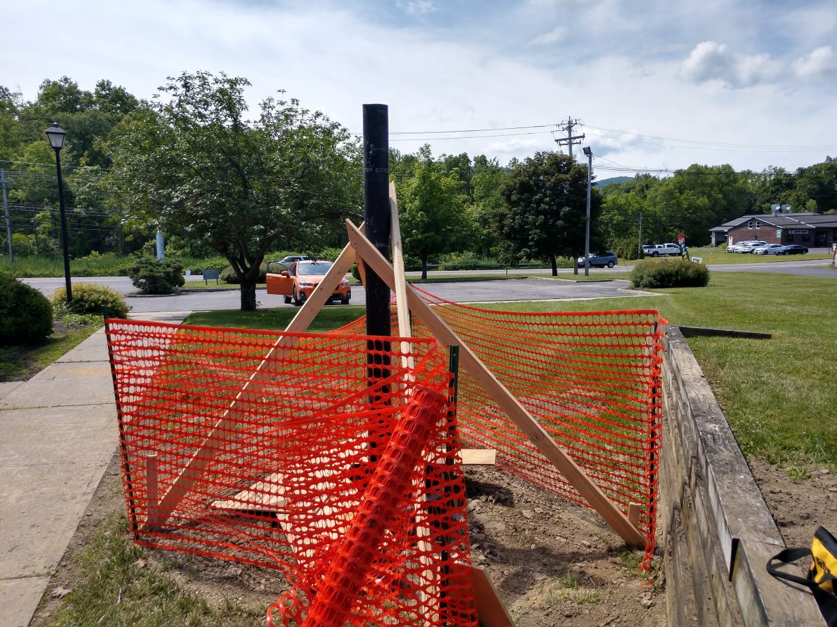
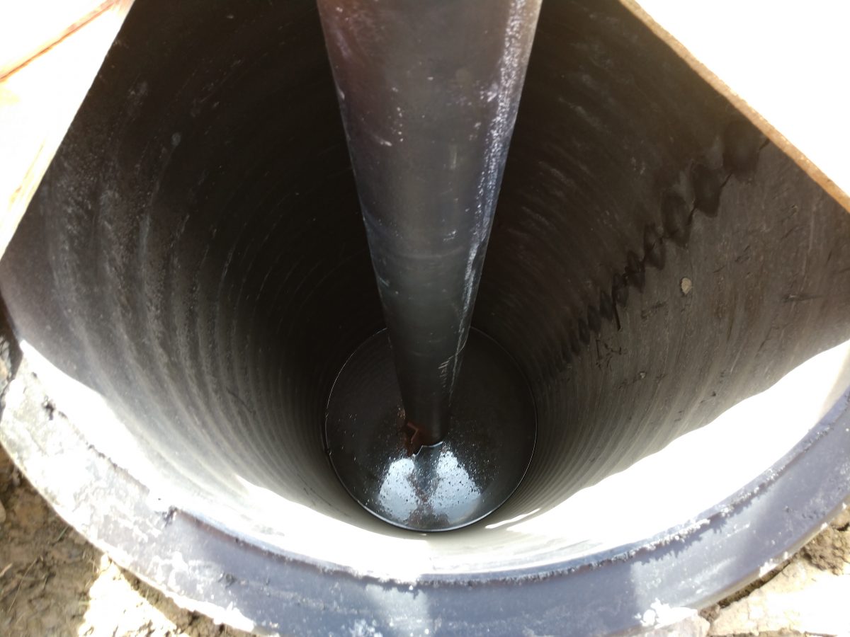
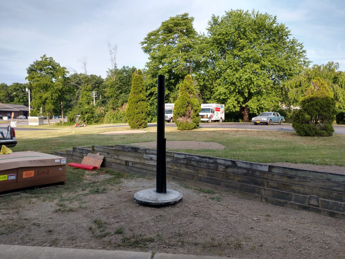
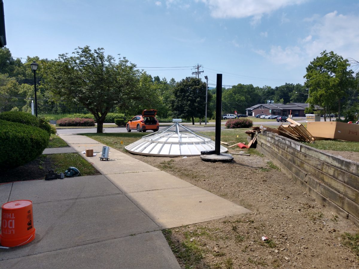
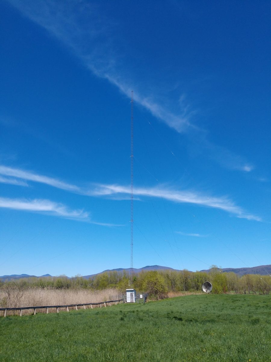
The new replacement tower has been constructed. It is the exact same height as the old tower but has a twenty-foot pole on top instead of a normal tower section. The pole was installed to mount the translator antenna. In addition to that, there will be other wireless services installed on this tower.
WKNY will have a six-wire skirt installed in the next few days. As this tower is close to 160 degrees at 1,490 KHz, the skirt can go anywhere from 60 to 120 degrees up the tower.