So sent wireless operator John “Jack” Phillips on the night of April 14th, 1912, and likely sealed the fate of some 1,514 passengers and crew of the RMS Titanic, radio call sign MGY. That message was sent in response to the radio operator on the SS Californian/MWL, who was attempting to report icebergs nearby.

Of course, it would be a gross error to blame the sinking of the Titanic on the radio operator, he was but one small link in a long chain of events that unwound that fateful night one hundred years ago. Beginning with the ship’s design and ending with the Captain of the Titanic, Edward Smith, many seemingly unconnected decisions lead up to the ultimate disaster that befell the Titanic.
After about four days at sea, during the late morning/early afternoon of April 14th, the Titanic began receiving wireless messages indicating “growlers, bergs, and ice fields” were in the area. The Captain decided to alter the ship’s course to the south, out of the supposed ice fields.
In spite of numerous reports of nearby ice, the Captain did not order the ship to reduce speed. It continued on at 22 knots (41 kp/h) up until the time it struck the berg. Lookouts were posted in the crow’s nest, near the bow, to spot icebergs. This was considered normal operating procedure at the time but is the most significant factor in the collision. A number of nearby ships had spotted ice and had greatly reduced speed or stopped for the night. Further exacerbating the situation, the lookouts on the Titanic did not have binoculars, which was due to a mix-up before they sailed from England.
Some of the ice reports received later in the day and evening did not make it to the bridge. Wireless operator Jack Phillips was either repairing a malfunctioning spark gap transmitter or was sending messages from passengers to Cape Race Radio/MCE, Newfoundland. At the time, the (wireless) radio operators were not a part of ship’s company but rather were employed by the Marconi Company for the purpose of sending messages for profit. Any notion of safety or distress communication was an afterthought.
The SS Californian, the closest ship to the Titanic at the time it sunk, was attempting to broadcast another ice warning to all ships in the area at about 10:30 pm. The message was broken off by Phillips with a terse: “SHUT UP! SHUT UP! I AM WORKING CAPE RACE” At about 11:30 pm, Cyril Evans, the Californian radio operator closed the station and went to bed. Ten minutes later, the Titanic struck the iceberg.
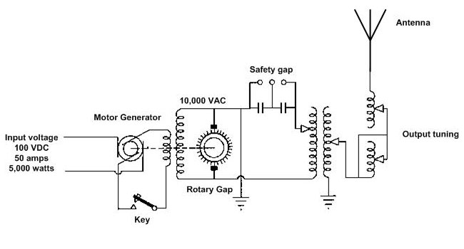
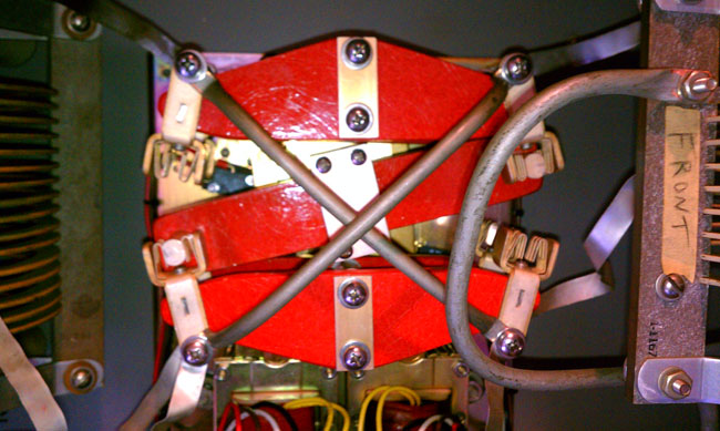
The Titanic used a 5 KW synchronous rotary spark gap transmitter, which was state of the art at the time. The power is measured at the input of the DC motor. Considering the efficiencies of the motor and generator, the ability of the spark gap to generate RF, and the efficiency of the tuning circuits and antenna, the actual power radiated by the transmitting antenna would have been significantly less, on the order of a couple of hundred watts. The above schematic is not exactly the same as the unit installed on the Titanic, as the meters and additional controls for motor speed and generator voltage have been omitted. Additionally, some sources report the transmitter as a 1.5 KW non-synchronous unit. The difference between the two would be very apparent in the sound of the received signal; a synchronous transmitter had a tonal quality to it versus a non-synchronous or simple spark gap, which sounded like hissing. Wireless operators from shore stations and other ships who worked the Titanic reported that they were using a synchronous unit.
The transmitter used two frequencies; 600 meters, or 500 KHz, and 300 meters, or 1,000 KHz. Because of these frequencies, the maximum range during daylight hours was about 200-400 miles (322-644 km). At night, the ranges were considerably more, 1,000-2,000 miles (1600-3200 km), which is typical for medium frequencies, including the AM or standard broadcast band in use today. Thus the effort by the Titanic radio operators to clear the backlog of message traffic during darkness, when Cape Race was about 374 miles (602 km) away.
Another part of the problem was with the transmitting and receiving apparatus itself. The transmitters were crude and generated broad harsh signals. The receivers were also very broad, and nearby transmitting stations could easily wipe out all frequencies on early receivers. That is what likely prompted Phillips’ outburst, something termed today as blanketing interference. Vacuum tubes (aka valves) had yet to be accepted for widespread use as amplifiers and most receivers were simple tuned circuits connected to a detector of some type. As such, receivers were far less sensitive and selective than they are today.
Interestingly, the Titanic had both types of receivers on board. The main receiver was a tuned circuit with a Marconi Magnetic detector (aka “Maggie”) and a valve receiver as a backup. The valve or vacuum tube was likely a simple diode detector connected to a tuned circuit.
After the collision, Jack Phillips stayed at his post sending out distress messages and communicating with other ships en route to assist. Long after the Captain told the radio operators they were dismissed, Phillips persisted until power was lost and the radio room began flooding. He perished shortly after in the 28° F (-2°C) water, however, assistant operator, Harold Bride, survived.
There is also some bit of discussion about the rudder commands given after the iceberg was sighted. Most accounts say, First Officer, William Murdoch, gave the command “Hard over starboard” which would be the equivalent of the right full rudder, effectively pushing the back of the ship to the left.
As rudders work, the amount of water flowing over the rudder determines its effectiveness or loading (resistance to water flow). With the center screw turning at full speed, the rudder would have quickly loaded and pushed the rear of the ship away from the center line by re-vectoring the water coming from the propellers. There is no way to know if this would have changed the outcome as not enough is known about the maneuverability of the Titanic. Her sea trials consisted of about seven hours of sailing time before passengers were embarked.
The next commands issued were “full astern,” on the engine room telegraph. Because of the design of the ship, it took about thirty seconds to engage the rudder and backing engines. The ship continued straight ahead at 22 knots (11 meters per second), traveling 372 yards (340 meters) before beginning to turn. The center screw had no reverse, so it was simply stopped. Once the engines were reversed, the rudder lost much of its effectiveness due to turbulent flow and stalling. The ship could not maneuver around the iceberg, striking it in a glancing blow springing the hull plating in five forward compartments on the starboard side.
As it was the Titanic’s maiden voyage, the first officer did not have much deck time and was likely less familiar with the maneuvering characteristics of the ship versus other ships he had conned. On most other ships of the time, including the SS Californian, which had just completed the identical maneuver, that combination of rudder and engine room telegraph commands would have been appropriate to stop and swing the ship around the berg.
The SS Californian was within sight of the Titanic as it sunk, observing several “rockets” (as many as eight) being fired. When informed of the rockets, the Captain of the Californian asked for their color but did not move to investigate or wake the wireless operator. According to some of the Californian bridge crew, the Titanic looked strange in the water, like something was wrong. The Californian attempted to signal the Titanic with a blinking light, which was not acknowledged. Inexplicably, the Californian never attempted to investigate further until 5:30 am the next morning when wireless operator Evans was back on duty and reported the sinking to the bridge.
Therefore, the entire chain of events that led up to the disaster includes:
- Too few lifeboats for passengers and crew
- Not enough training in the deployment of lifeboats
- Very short sea trial period for the ship’s crew before passengers were embarked
- Overconfidence in the water-tight door system in keeping the ship afloat
- Binoculars for lookouts were not procured in time for sailing
- The ship’s rate of speed is too fast for the conditions, with numerous reports of ice in the area
- The ship’s radio operator dismissed ice report from the nearest ship (almost within view at the time) so he could continue to send paid message traffic
- The combination of helm and engine room telegraph commands did not produce optimum maneuvering
- Failure of the nearest ship to recognize distress flares (or rockets) as such and render assistance
Change any one of those nine things and the outcome might be entirely different. Something to ponder.
The result of this disaster was the formal codification of shipboard safety requirements known as SOLAS or Safety Of Life At Sea. Those standards include the transmission of distress signals, distress communications, numbers of lifeboats, radio watches, fire suppression systems, and training for passengers and crew. Currently, the distress communication system is known as the Global Maritime Distress Safety System or GMDSS.