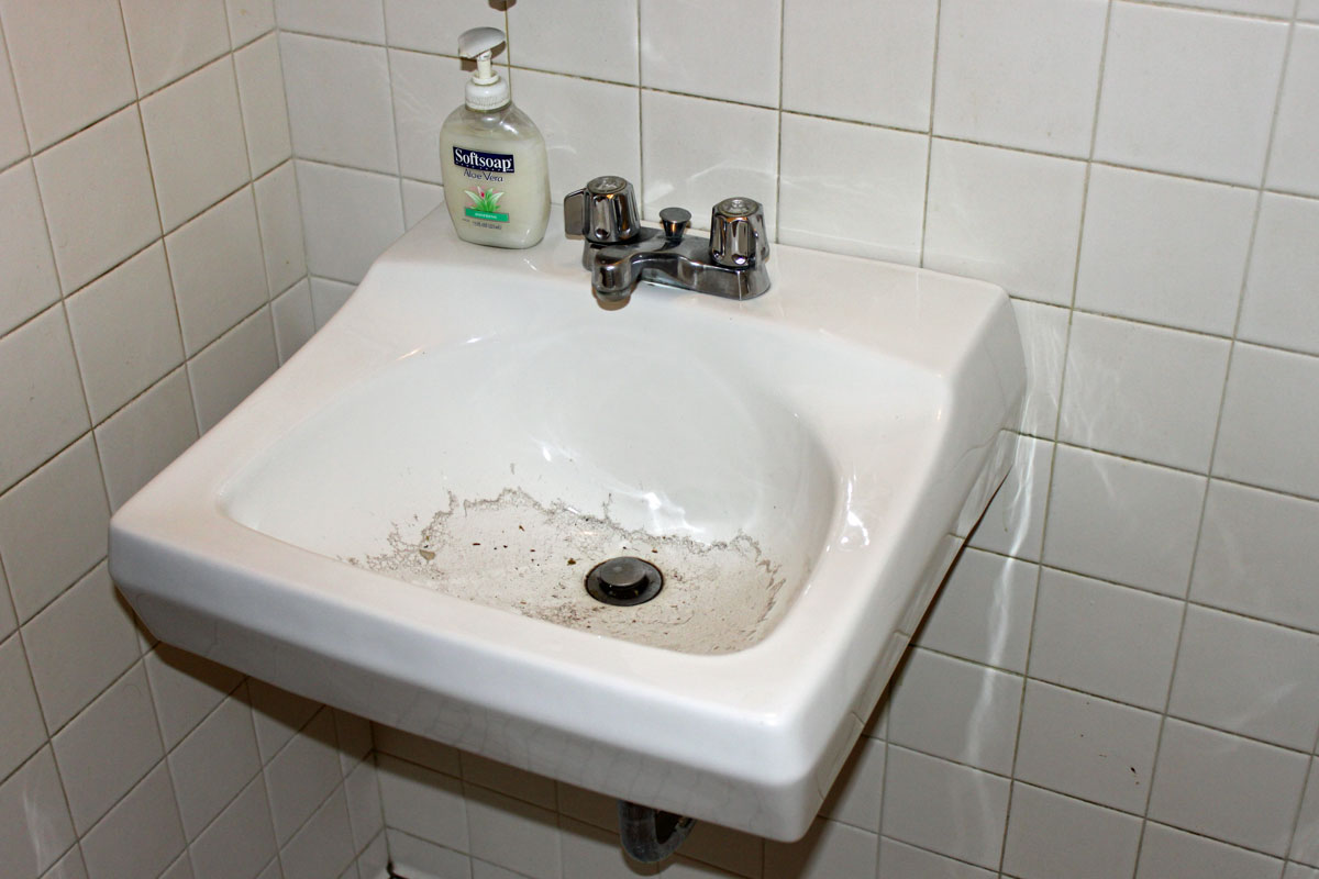
Especially when that sink is located on the second floor, above the studio on the first floor. ‘Tis but a small thing really, one of those little details, but in light of the sink also being clogged, it becomes very significant. That, coupled with the fact that the building is uninhabited at night and disaster is afoot.
Clogged sink
The water was running slowly all night…
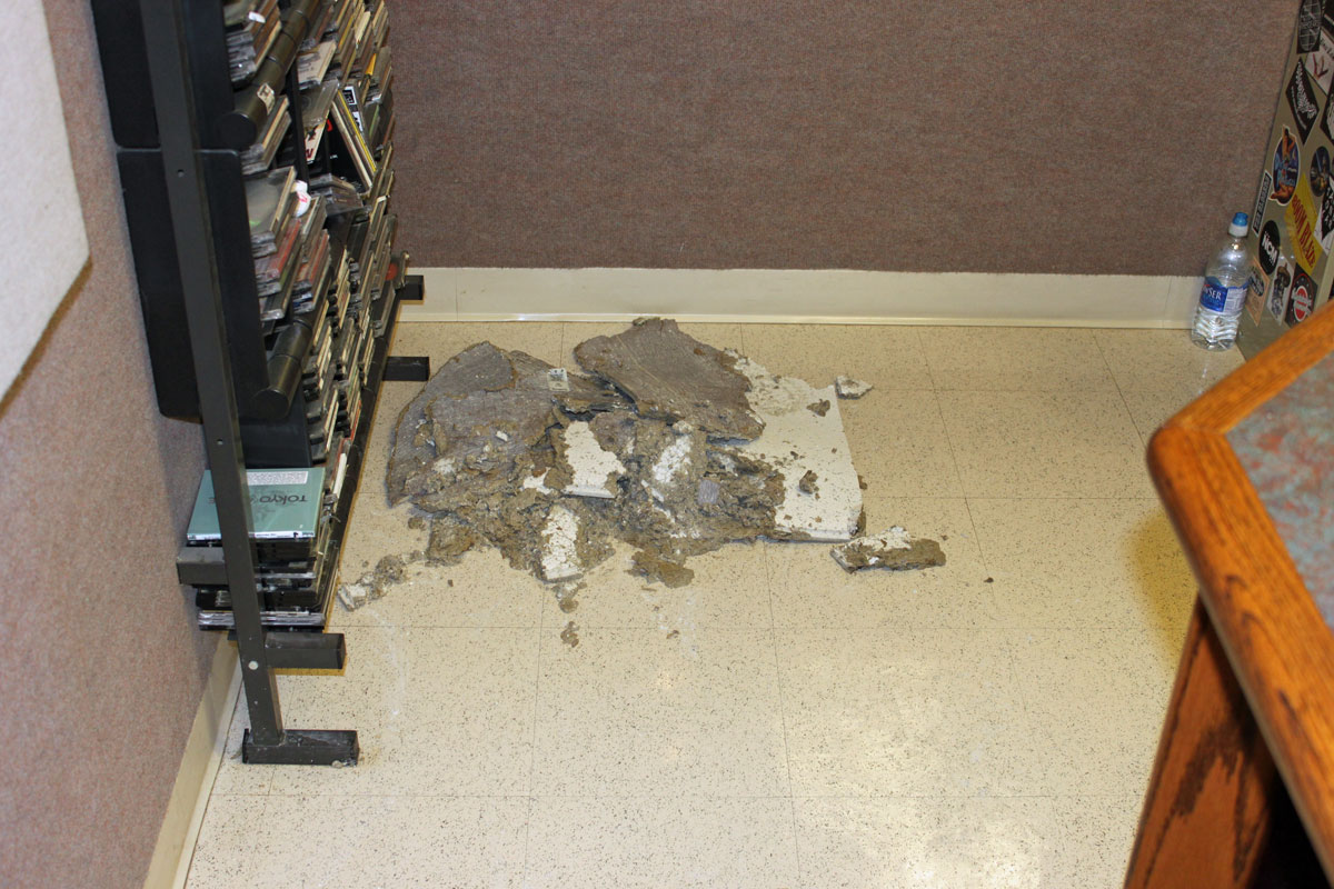
Wet ceiling tiles
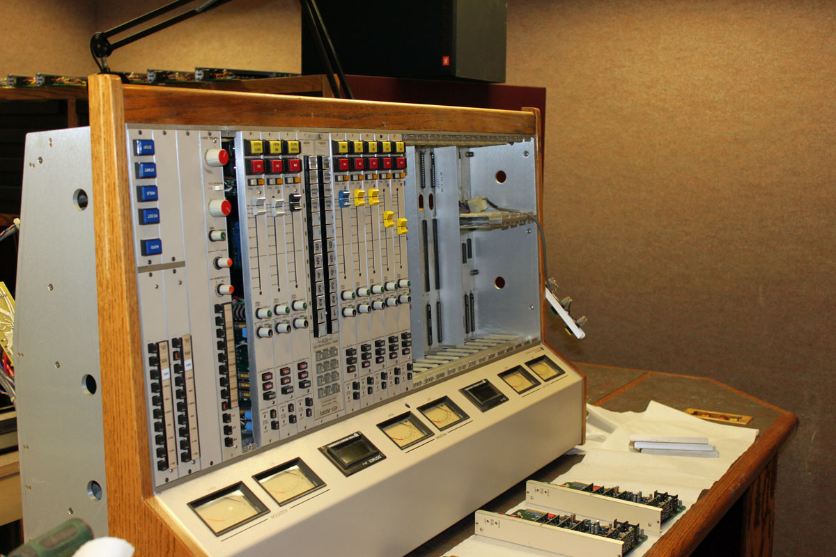
It filled up the sink. It ran across the floor. It soaked the carpet. It seeped into the sub floor and out of the ceiling on the first floor and then into this nice Pacific Recorders BMX III console.
Pacific Recorders BMX III console, drainingPacific Recorders BMX III console, draining/drying
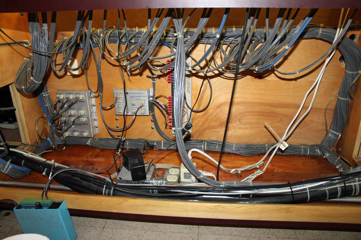
Do you know that burning electronic/plastic smell? Yeah, that’s it, mixed with stale funky water, wet wood and a nondescript mildewy odor; that is what the room smells like. Very pleasing. The furniture below the console was soaked too:
Studio furniture after water damage
Some of the input module edge connectors; didn’t fair so well:
PRE BMXIII burned edge connectors
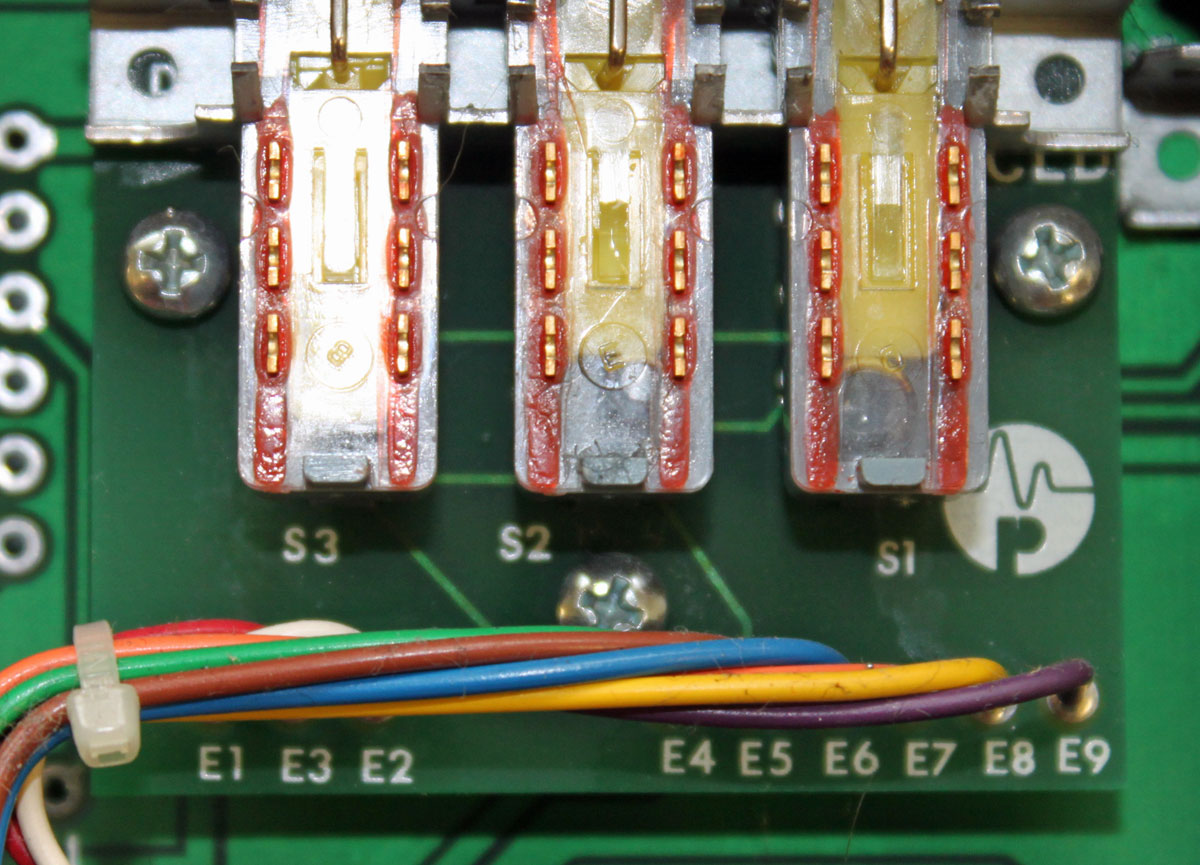
The backplane for the power supply buss has to be replaced and these switches with the water bubbles in them, have to go too:
Pacific Recorders BMXIII buss select switch full of water
We dried out the furniture with an industrial strength hair dryer. By three PM we had unsoldered all of the bad parts and cleaned off the modules and the console back plane.
Parts for repairs are on order from Mooretronix. I doubt this will be repaired before next Tuesday.
Somebody came in and was all “awww, this sucks bla bla bla.” Well, maybe, but I get paid by the hour and frankly, there are much worse things that I could be doing…
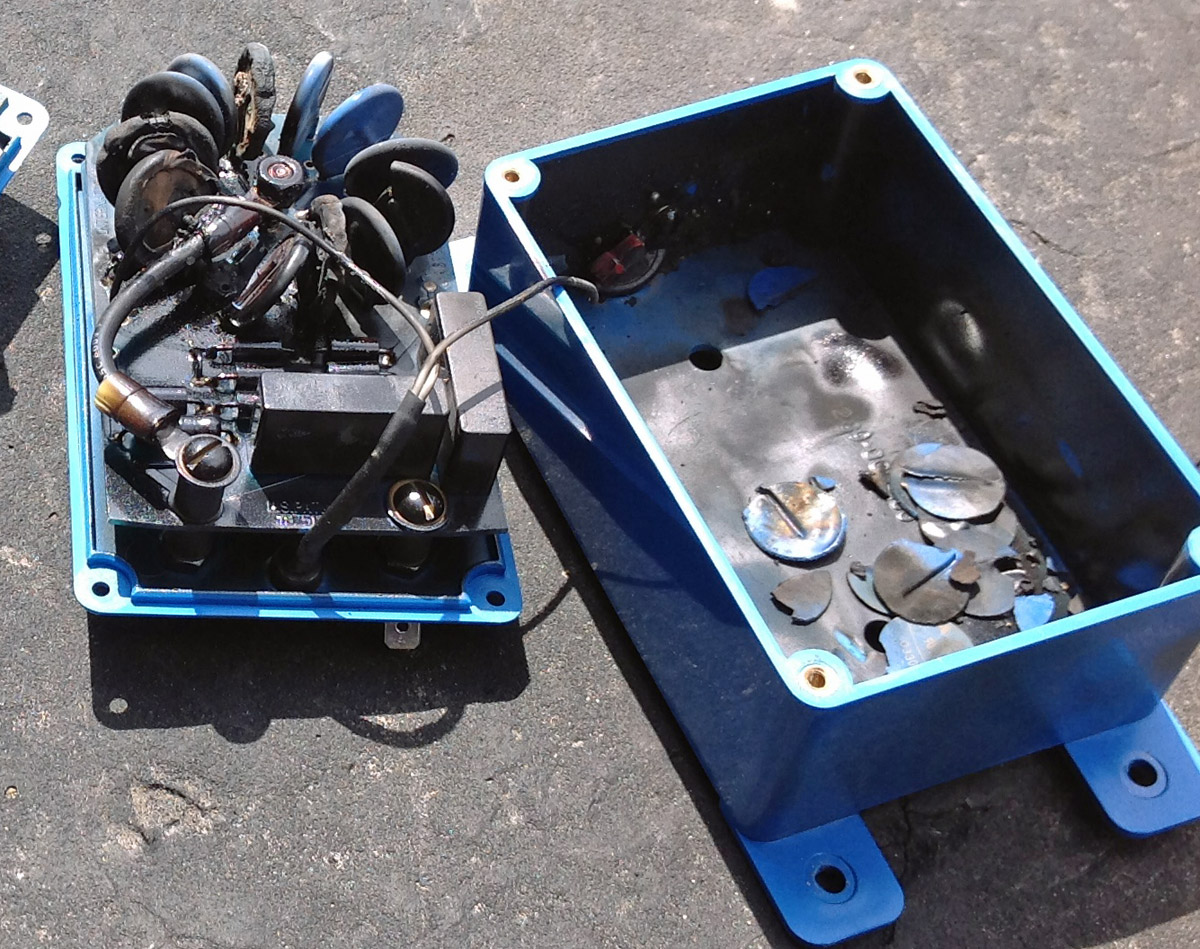
This is a picture of a surge module taken from an LEA series type surge suppressor:
LEA 600 volt MOV module
Looks like it took a pretty significant power hit, enough to explode several MOVs. This site is at the end of a long transmission line that stretches across an entire county. Over the years, the station has made many complaints to the utility company about the quality of their power and the frequency of interruptions encountered at this transmitter site. Occasionally, something will happen. Often times it is the figurative shoulder shrug.
This is a universal truism that can also be expressed as “Murphy’s Law.” I don’t rightly know how Murphy received credit for this, however, I chalk it up to either the luck of the Irish or the gift of self-promotion. Either way, that principle was demonstrated again with a 950 MHz STL link between Mt. Beacon and Peekskill, NY for WHUD.
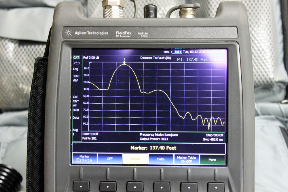
I noticed, while doing some transmitter maintenance, the receive signal strength of the STL had dropped from 300 µV to 30 µV. That is an alarming development. Therefore, we scheduled a tower crew for the next day, not wanting to go off the air over the coming holiday, which would be a sure bet otherwise. Upon arrival, the tower crew noticed a strange thing in the STL transmission line at the base of the tower, which looked like some type of a splice. Truth be told, I have been associated with this station since 1999 and had never noticed the splice before. This STL system was installed in 1998 when the station’s studio moved from Peekskill to Beacon. I can say, of all the things that have gone wrong over the years, this STL system was always very reliable. Regardless of that, I quick check with a spectrum analyzer showed a 3 dB return loss at 137 feet (41.75 m), exactly the distance from the transmitter room to the base of the tower.
3 dB return loss, distance to fault 137 feet
A 3 dB return loss coincides exactly with the drop in received signal strength at the other end of the path. Thus, the tower crew took apart the splice and water poured out of it. I would estimate at least 4-6 ounces of water (180 ml), perhaps more.
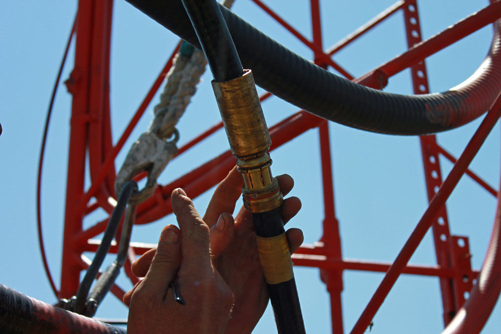
7/8 coax cable splice connector, opened up
We then began to take in the details:
The 7/8 coax coming out of the building was Cablewave FLC78-50J
The 7/8 coax going up the tower was Andrew LDF4-50A
The splice connector was Andrew L45Z
The center conductor threaded connector did not fit properly into the Cablewave cable, it was too loose.
The cable was chaffing on a tower leg, about 50 feet above the splice because it was not properly secured to the tower
The 7/8 splice connector was missing an O ring on the backnut of the Cablewave cable
Thus, water ingress causes the high return loss. Problems with this system began immediately after Hurricane Irene, at the end of last August. We were able to make a temporary fix using two type N connectors of the proper manufacturer for each type of cable. The radio station returned to air just before noon, about 45 minutes after turn off. After the repair, the return loss dropped to about 20 dB, which is good.
The permanent fix is for the entire run of cable from the transmitter room to the STL antenna to be replaced. That type of line splice should have never been used on a 950 MHz STL, and it was certainly wrong to mix cable types with an Andrew connector. Those little details will always manifest themselves eventually.
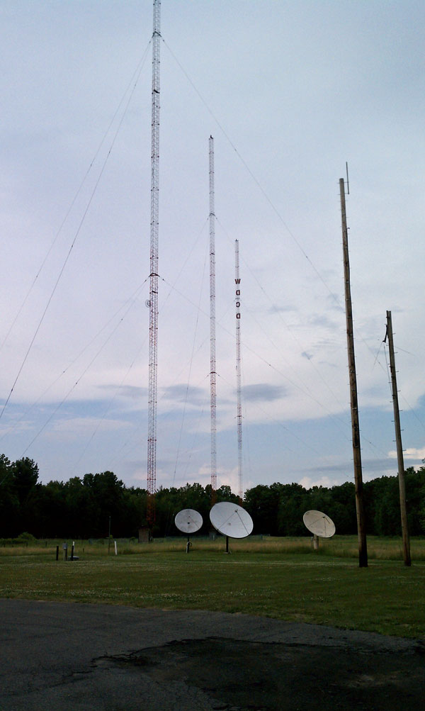
This picture reminded me of something that happened early on in my radio career:
WDCD three-tower array, Albany, NY
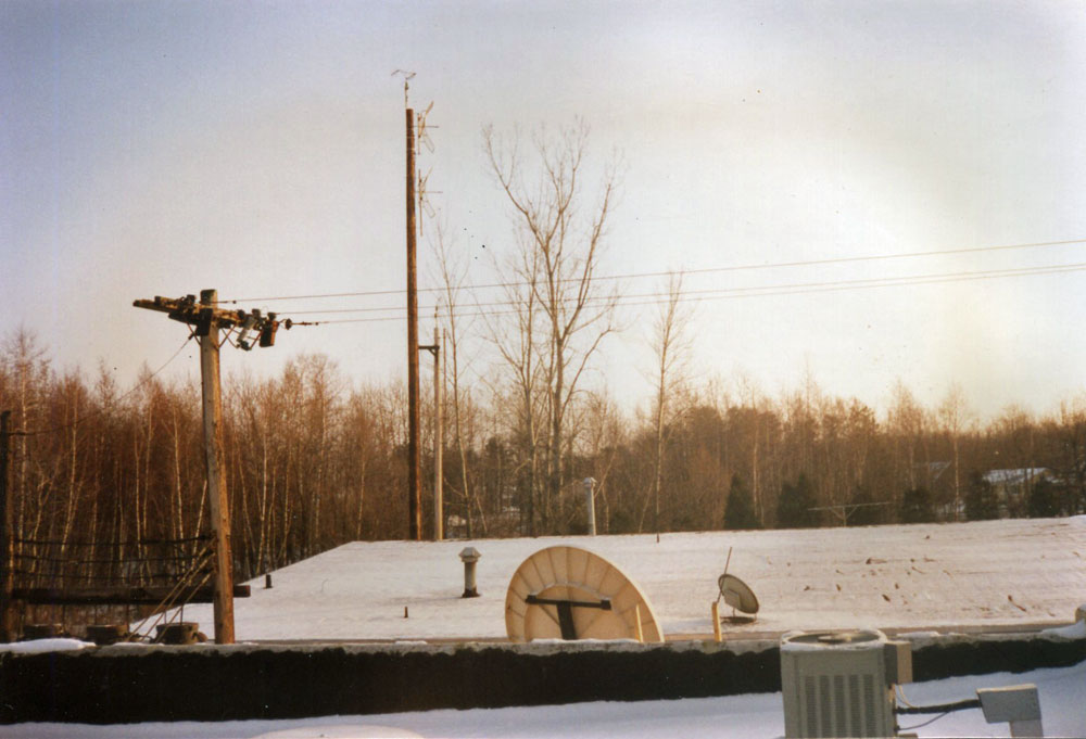
This is another view, looking across from the roof of the transmitter building before the former studio building was removed:
WFLY STL antenna, circa 1992
The story dates back to 1990 or so. In the second picture, one can see two Scala PR-950U Paraflector antennas. These are the STL and TSL antennas for WFLY. They are on wooden utility poles because of the WPTR 1540 KHz antenna system is behind the poles, out of the picture to the left. As you can see in the second picture, these poles were immediately behind the studio building, known as the “Gold Studio, ” the name itself being pure propaganda.
Also, in the second picture you can see behind the poles, a pair of poplar trees. The reason for the second, taller pole was because across the street, out of the picture to the right, there was a stand of poplar trees which were growing up into the path of the WFLY STL system.
When this was noticed, then General Manager, John Kelly, tactfully approached the property owner and asked if the radio station could cut the “popular” trees down. Of course, the property owner wanted much money to do this. There were many telephone calls and discussions on how to kill the “popular” trees and other, not-so-ethical solutions to this growing problem. Finally, it was decided that it would be simple and less expensive to install the taller utility pole.
Thus, Northeast Towers found the utility pole and came to install it. In this area of Albany, the soil is a sandy loam, which required many hands digging and back bracing in the hole before they placed the pole in the ground. As it is a seventy foot pole, a good 12 feet was placed in the ground and the hole was backfilled with concrete. That is why the pole still stands today.
Naturally, all of this work is taking place on the hottest day of the year. Also, it stands to reason, the guy in the hole doing the manual labor is the oldest, most out-of-shape person on the crew. After lots of grunting and swearing, our man comes out of the hole looking whiter than the driven snow and sweating profusely. He kind of staggered into the back door of the building and collapsed on the floor just inside the back door. At this point, he was in full cardiac arrest. The promotions director, whose office was closest to the door, called the ambulance.
Fortunately, the board operator on WPTR was an EMT with the local fire department. After his pager went off, he ran out to his car, got his EMT bag and arrived on scene within seconds. He was able to start CPR quickly. In the mean time, a crowd had gathered out in the hallway. John (the General Manager), hearing the commotion, storms out of his office and down the hallway. He gets to the edge of the crowd and yells:
“WHAT ARE YOU PEOPLE DOING HERE? DON’T YOU HAVE JOBS TO DO? AND WHAT IS THAT GUY DOING LAYING ON THE FLOOR?”
The good news is, the guy survived, thanks in no small part to the quick action of the board operator.